Remarks on a LT3045-based linear regulator
Return to home page
In order to ensure lowest possible noise in the laser output, I use a dedicated low noise, linear power supply for the diode driver; the point being that there is always some feedthrough via the regulating transistor of the diode driver (reducing ripple rejection), so it is important to have an as clean as possible power supply to begin with. Out of curiosity I played with various LT3042/LT3045 ultra-low noise boards, available eg. from Aliexpress.
The board based on a single LT3042 had an issue, in that the voltage regularly dropped by about 4 volts after a few hours, which is surprising given a light 100mA load and moderate 25C ambient temperature. Cooling the LT3042 by freeze spray identified it as the culprit - even though the current mainly goes via an extra PNP power transistor (that I put on an external heat sink, the internal one was bogus). Thus: nogood for unclear reasons.
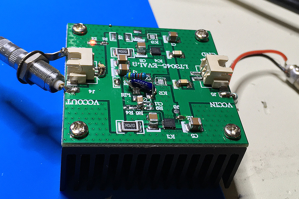
Then I got a board with two LT3045 in parallel, which supposedly can do 1A (when keeping the dropdown voltage small, like 0.5V). There is no extra power transistor (hence no compromised ripple rejection), and there was the promise/expectation that the output noise was in the low uV/pp range. Not that this would be too important for the present application as post-regulator, but there was an idea at the horizon to use a similar circuit for a laser driver as a whole. Thus I started to look into the noise behavior.
First impression: awful! The noise was in the oder of 1mV/pp, about 100 times worse than the specs (below, a gain=10 isolation pre-amplifier was used, so 10mV/pp corresponds to 1mV/pp real):
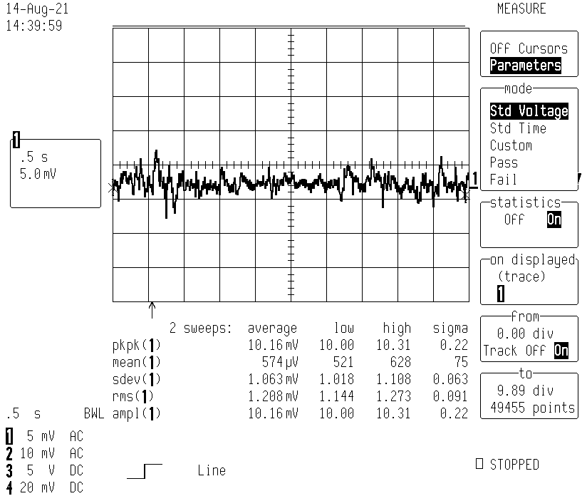
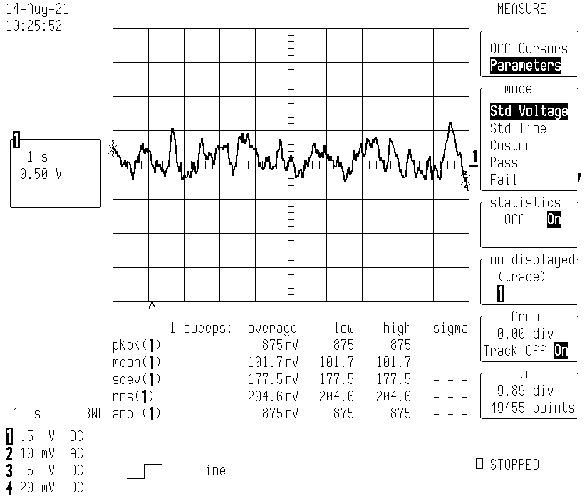
The main culprit was found to be the SMD trimmer. So I replaced it by a 50K PTF-56 resistor which yields 10V, and also I replaced the 4.7u capacitor next to it which was a tiny 0603 chip with just 40MOhm isolation. From the data sheet it is clear that these two components are critical for stability and low noise. Indeed the noise dropped by a factor of 25 to about 40uV/pp (0.1-10Hz):
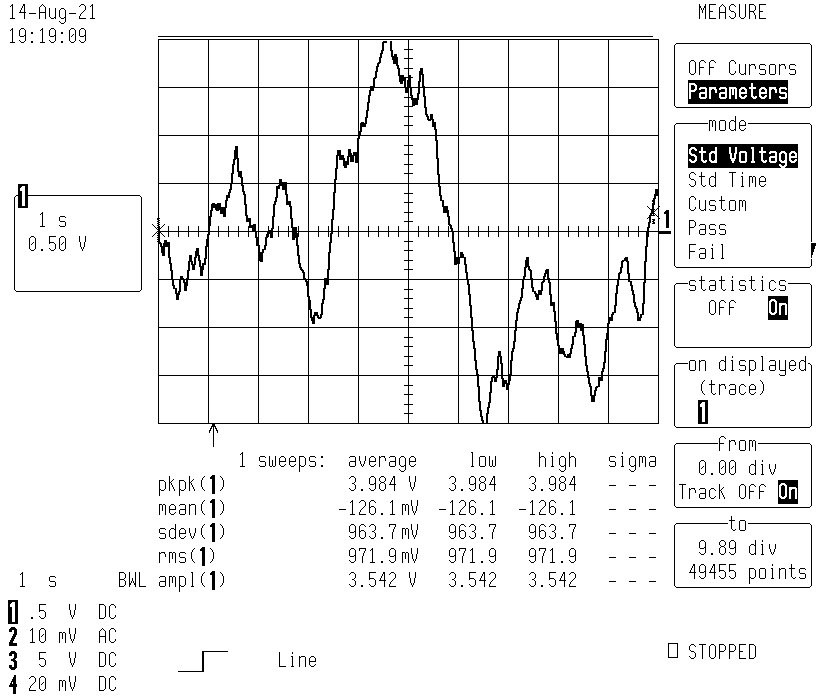
(here the total pre-amplifier gain was 10^4 so 1V on the scope corresponds to 10uV).
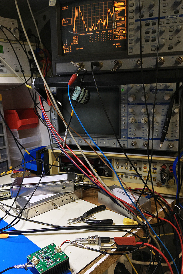
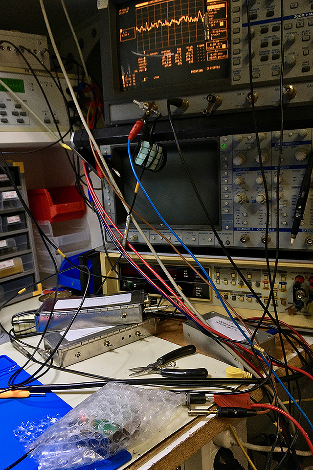
Given the sensitivity of the high-impedance circuit, it is very susceptible to air currents. After putting some bubble wrap around it (seen in the foreground), the noise further dropped to about 9uV/pp:
... fine for me, perhaps it could be further reduced by watertight metal shielding, etc.
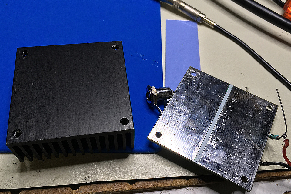
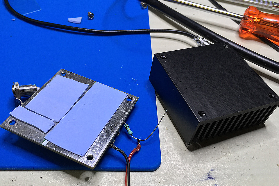
Another point of concern was the cooling. I was not really surprised to find that the PCB was just screwed on top of the little heat sink, which means a very bad thermal contact. I added a layer of thin silicon thermal pads to improve on that:
Current: Vers. 0.9 - August 2021
Return to home page