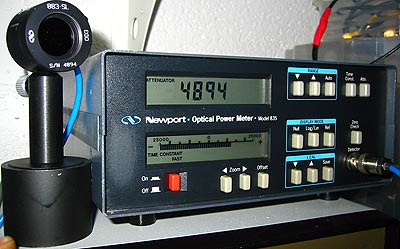
Newport builds wonderful photonics equipment, and used surplus parts regularly appear on Ebay. I had been a bit quick in bidding separately on an 818-SL detector head and on an older Model 835 power meter, and realized only later that these power meters have the calibration data for a specific detector head stored in an internal Eprom (unlike the newer meters like the 1830 series that use detectors with individually attached calibration modules). For the 835 model that I got, the Eprom was programmed for an 818-IR infrared head, which was no use to me. On the other hand, I got the 818-SL detector head (incl the 883-SL detachable attenuator) together with its calibration module, so I inquired with Newport whether they would transfer the data from the calibration module to the 835 Eprom. However, they told me that they wouldn't do this for those old meters any more - so it seemed to me to have wasted a few $$$ on completely useless equipment, and I pondered to write it off.
But the thought that I do have all the relevant data are just there in the calibration module in front of me bugged me, and I decided to give a little reverse engineering a try and figure out how to copy the data from the cal module over to the 835 Eprom. At any rate, I had zero knowledge about microprocessors and programming Eproms and all that, so at least I could learn something interesting from doing this. If successful, that would save my 835 meter from unnecessary retirement, and perhaps others' too - I see 835 meters without matched detector heads popping up on ebay all the time, and all these should be as such pretty useless for almost anybody. Perhaps that's why they are much cheaper as compared to the more modern series 1830 and up meters, which are based on external calibration modules but otherwise do not offer so many more essential features; after all, power meters are essentially nothing but just simple current amplifiers, dressed up with a more or less fancy digital interface. Indeed, for almost all purposes, the model 835 with its large dynamical range (nW to 2W) and accuracy is as good as any one of the more modern power meters.
So perhaps the following notes are helpful to other people as well - I won't be specific in giving details of the code I reverse engineered in order not to infringe copyrights, but rather just outline the procedure so that a knowledgeable person can repeat it. At any rate, anyone with a Eprom reader can read out those chips and copy them, so what I write below is no secret; but it can save people from doing duplicate work. For this, a brief overview of the data formats might be helpful.
The Eprom in question is located to the right of the opened instrument and carries an identification sticker, in particular displaying the 818-XX type of detector to which it matches, its serial number, the calibration date and the software version. The (UV erasable) Eprom is an older M2764A NMOS type, which can be easily gotten from electronic distributors. It carries 8K bytes of data, and shares its first 1K addresses with an onboard static RAM HM6514 (that's why its first nonzero memory address is at $400).
The data were conveniently read out via a Willem programmer (which can be conveniently obtained via Ebay) and written on a file. Detailed reverse engineering revealed the following structure. Starting from $400, the first four bytes carry the serial number of the detector, the format directly encoding the LCD 7-segment display. The next four give the serial number of the model 883-XX detachable attenuator that comes with the detector (and which usually has the same serial number). Then there are two times three bytes of unknown meaning, which seem to refer again to detector and attenuator. The addresses $40E and $40F carry the lower (lmin) and upper (lmax) wavelengths divided by 10 (eg $28=40 and $6E=110 refer to the 400-1100nm range of the SL detectors). Then there are 8 bytes of unknown meaning (overall normalization of the data?) At $418 there are then cal data entries, first N bytes for the detector and then N bytes for the attenuator, where N = (lmax - lmin)/10 + 1 is the number of 10nm steps plus one. For example, for the SL detectors, N=71.
Then, after a couple of zeros, from $540 onwards there are again N+N cal data bytes, and these are the least significant bytes LSB of the cal data, while the previosuly mentioned N+N data correspond to the most significant ones, MSB. In other words, the complete calibration constant for the i-th wavelength is given by 16*16*MSB(i)+LSB(i), where MSB(i) corresponds to the i-th byte in the first ($418) block of cal data and LSB(i) to the i-th byte in the $540 block of data.
All what is needed is to replace this data discussed above, with those from a cal module. Before we come to that, let's just mention that the system firmware starts at $668 - first there a few lines of software version and display string data, and then at $716 the actual program for the MC146805E2 microprocessor starts which is of no concern to us here.
Note: the above addresses apply to software version A6. For version A5, some addresses are slightly different but the general data structure is the same. At any rate, the starting address of the actual program is always given by the very last two bytes of the Eprom. Note also that sometimes a detector has been calibrated without an attenuator; then the corresponding attenuator data fields are filled with constant data $3f fe=16382, and the "attentuator" button on the power meter is disabled.
Data format of the 818-XX calibration modules
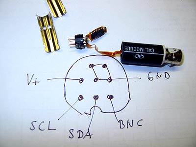
The main problem was to figure out how to read out the data from a cal module, which implies knowing the pinout of the 8-pin mini-DIN connector. I couldn't find any other way other than acquiring an extra spare cal module to take it apart. Some of its pieces had been glued together, so that some destructive work was necessary. Fortunately, I was able to put it back together in a still fully functional manner, so that the module was not wasted.
It turned out to contain an X24C16S serial EEprom in SOIC package, which communicates via an I2C bus. The pinout, when facing the module, that I found is shown below to the left, together with the disassembled cal module; here, SDA and SCL refer to the I2C bus, and BNC carries through to the BNC plug at the other end.
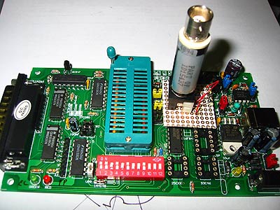
Next issue was to read out the data, again via the Willem programmer. All what was necessary was to put together a little adapter that maps the pins of the cal module to the DIL-8 socket on the Willem programmer that takes care of programing X24xx devices. It was then a snap to read out the data from the cal modules and examine them; see the pic on the right.


The first part of the data turned out to be identical to the data format used in the 835 Eprom, and that was good news! That is, address $00 in the X24C16S serial EEprom corresponds to address $400 in the M2764A parallel Eprom, and the first two blocks of data correspond to the same data as before, and comprise the 2N+2N bytes of cal data of detector and attenuator. The data sets differ from adresses $200 and onwards, which contain type and serial numbers of detector and attenuator and other data.
Moreover, at $400 there seems a repetition of detector data and at $600 there is a repetition of attenuator data, however in a different format now: they come each in 2N bytes each which correspond to 16bit integers. I am not sure what the purpose of those data is; surprisingly, these data are slightly different to the sets of data between $00 and $200! My tentative interpretation is that these data are the "old" data prior to the most recent re-calibration - somewhere on the Newport site it is mentioned that they keep the old data in order to spot trends in calibration changes. So why not having them stored in the cal module as well?
Transfer of 818 calibration module data to the 835 Eprom
From the above notes, this should be easy now: copy the contents of a working 835 Eprom into a file and then copy the first two blocks of data of the 818 cal module over the first two blocks of non-zero data (starting at $400), and leave the data from $640 onwards untouched. This needs to be done with a Hex editor, of course. The new data then need to be written on a blank M2764A Eprom, again using eg. the Willem programmer. I had a few problems in writing the old Eproms I got, it turns out that the Willem programmer needs to be powered externally and not via the USB bus in order to avoid a voltage drop. Also, the burn voltage depends on the specific manufacturer, in my case it turned out that 21.5V were needed. Details and background info can be found at the Willem site.
And voila - the reprogrammed 835 meter with its newly matched 818-SL detector head worked flawlessly right from the first turn-on, and I found the calibration accurate within 2-3 percent as compared to my other (Laser precision RK-5720/RPK-575) power meters, for all wavelengths I checked and also with and without attenuator!
I am not yet 100% sure how to determine the absolute normalization factor to convert the stored data into responsitivities (mA/mW); though I believe that the normalization factor for the detector is equal to 16384, so dividing the data by this gives the responsitivity in mA/mW of the detector; this was inferred by feeding a precisely known constant current into the meter, and reading the display (however, for an 883-IR attenuator I found that the normalization factor seems to be 32768).
Note added: this has been figured out now - see below.
Plots of some read-out calibration data
Below, the left pics show the data for some bare 818-XX detectors, while the right pics are for the combined 818-XX detector/883-XX attenuator combos. Of course, these refer to the specific cal modules that I have, and the data will somewhat differ for cal modules matching other detectors. Note that the curves below show that the difference in sensitivity between detectors of the same type can amount to 10% or so!
These data are for a pair 818-SL detectors (note the sensitivity variations between the detectors):

These data are for two 818-ST wand type detectors:

These data are for a pair of 818-IR detectors (only for one had data for an 883-IR attenuator,
and these were folded back for values greater than 32768 resp 1):

...sent by a helpful person, thanks! It contains a summary plus new information on the encoding of the conversion factor, mA/mW.