Return to home page
I got another diode laser module with a broken diode. There was no label on the laser but it seems that it is a Melles Griot 56-CRH/S2832 rated at 15mW or even up to 100mW at 641nm or so; a data sheet is hard to find, but see at least here. Not being an single mode ECDL but rather a free running diode laser, there is nothing extraordinarily interesting for holography about it, but still, even a minor repair job with diode replacement can teach a little. So that's why.
Here is the original interior:
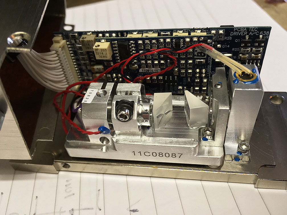
In the foreground, from left to right, we see the diode mount, then a collimator tube, then a pair of anamorphic prisms for beam correction, then a 1/2 lambda waveplate and finally a beam pickup with a photodiode. This is used for precise output power stabilization. This rests on a temperature controlled plate sitting on a TEC element, wired to a thermistor. Not shown is what is mounted to the case, namely a dielectric filter (?) on the inside plus a narrow-band filter mounted on the outside.
Puzzling is the following: from the anamorphic prisms one concludes that the beam exiting the diode must be vertically polarized. Consistent with this, the beam pickup contains a vertically angled glass plate, likely mounted in the Brewster angle to minimize losses. What is then the purpose of the expensive waveplate? It rotates the polarization to horizontal, apparently maximizing the loss in the beam pickup. Indeed, after substituting a new diode with vertical polarization, the power immediately jumped up by almost 20% when just removing the waveplate. So wtf...?
Also, the purpose of that second, inner output window evades me, as there is also the filter on the outside that looks silverish because it has such a narrow passband. It looks very dark red when looked through. Probably the idea of the latter was to minimize the entry of any outside light to the photo diode in order not to upset the power stabilization loop.
Exchanging the diode was not that easy as the original 5.6mm diode was glued to a 9mm adapter ring, which may not give good enough heat dissipation for higher powers. I had to fiddle around to optimize the heat transfer for the more powerful HL63643DG. There is no thread for adjusting the collimator, so that is also pretty cumbersome to deal with. On the positive side, there are three side-wise screws to center the diode with respect to the collimator. That has a very small focal length so produces a narrow beam. The spot size in 5m distance is perfectly round and of ca 0.5cm in diameter, so this is pretty good.
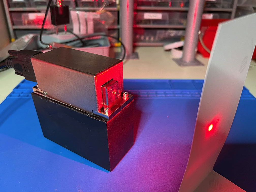
Eventually, after removing the PCB (useless without original controller) and rewiring, the running laser looked like this:
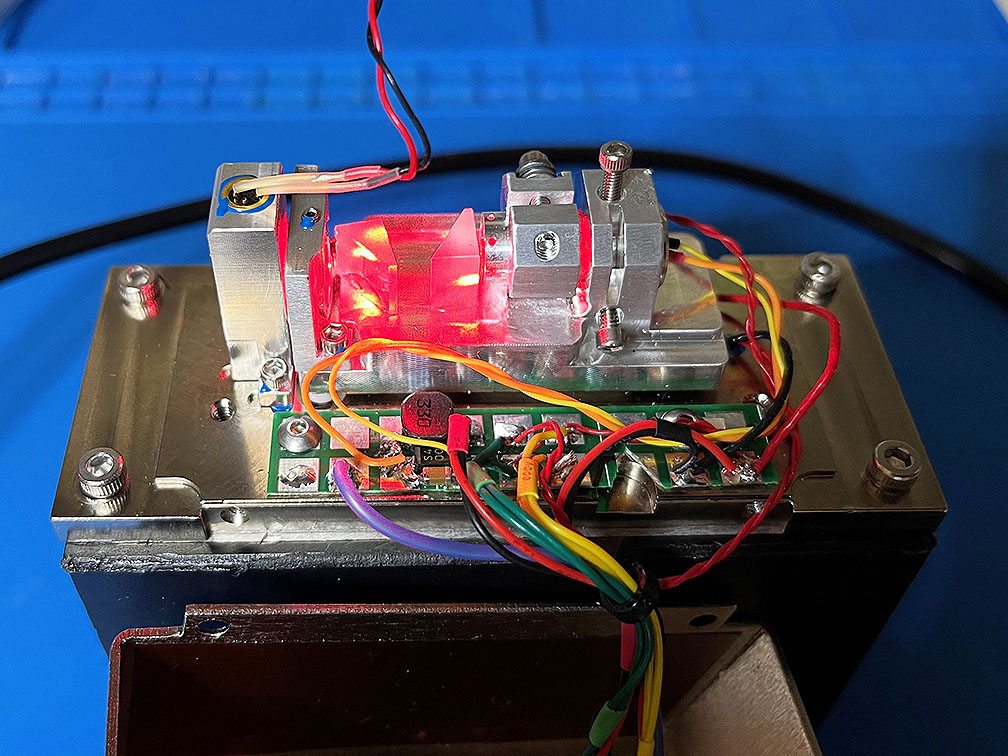
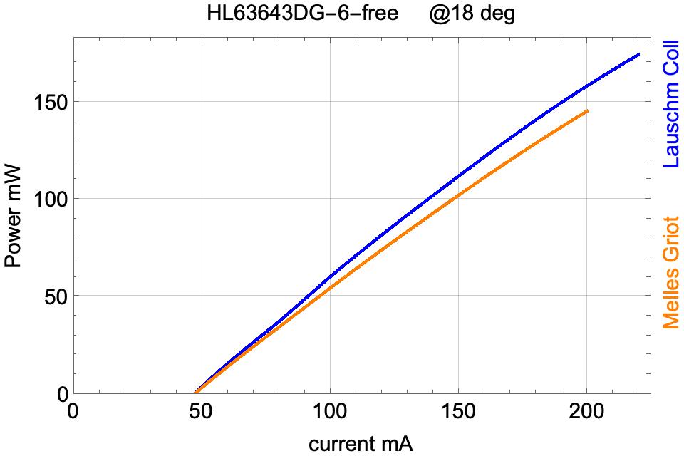
Later I removed the said waveplate. The power went up but still didn't match the output of the very same diode that I measured in a different setup:
This must be due to losses of the prisms - despite they seem to be coated, there is quite a lot of scattered light as is evident from the picture above.
However worse was the surprise that also the linewidth landscape scan now looks substantially different and less benign, as compared to the previous setup described here; minor reflections from the collimator, the prisms, and/or the output window may have shifted it around:
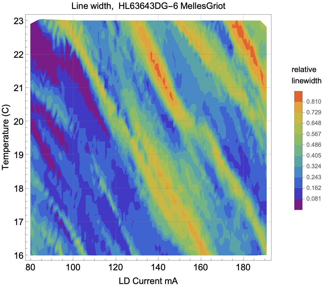
Therefore the current had to be reduced to about 105mA at 21.5C, and in total the maximal single mode power was only 55mW, as compared to 75mW of the same diode in a more basic setup.
Return to home page
Vers 1.0 7/2022