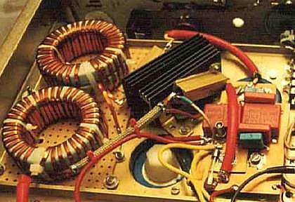
This is a separate unit as I couldn't find a place for the inductors and caps directly near the heat sinks. It consists of the toroidal chokes (one for each power unit, if there is more than one copy) and the high quality filter caps, plus some bleeder resistors. One needs to make sure that the caps are specifically suitable for switchmode applications (low ESR, capable of several amps at 10khz say). At any rate, they must be connected by very short and wide (low inductance) wires, taking several parallel if necessary. I used pieces of copper-clad epoxy board screwed directly on the cap, in order to have the lowest possible inductivity, and thus the maximal suppression of the switching pulses in the outout. The .1Ohm resistors in series with the inductors (to the right of the inductors in the pic) are for monitoring the current "sawtooth" waveform through the inductors (by displaying the voltage drop on a scope); they not necessary for operating the circuit, but come handy if permanently installed.
Typical current waveforms through the inductors, measured via the two
.1 Ohm series resistors
(vertically 5A/div):
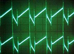
This shows good balance between the two mosfet units and nicely displays
how the current grows during mosfet switch-on and how it decreases during
switchoff (during which time the currnent flows via
the freewheeling diodes). Note the switching spikes which are spurious
and are induced into the scope probe (they are present even even when the
probe is not connected at all). Thus they are nothing to worry about.
Note that if N power units are used in parallel, each connecting to its own inductor, then the effective inductivity is 1/N times of that of an individual choke. Thus, if we want to keep the same minimal current for having continuous mode, we have to increase the inductivity of each of the N chokes by a factor of N. An easy way to do this is to stack N toroids together while maintaining the number of turns (so altogether we need N times N toroids); the payoff is a hugely increased (by N^2) power transfer capability.
Another remark: I was reading that a large capacitor across the ion discharge
tube would tend to lead to instability. The Omnichrome PS has another inductor
after the main filter cap, perhaps for exactly this purpose. However I did
not find any instability in running the circuit as-is with my NEC tube; perhaps
the .5Ohm shunt resistor has helped here. It may be that in other cases
an instability occurs, in which case one may either try to increase the
resistance in the anode circuit (which leads to high power dissipation, though),
or add a (high-DC-bias tolerating) inductor similar to the main storage inductor.