There is a great interactive web site that helps with the design, playing around with it is most instructive and gives some intuition in the problem. Specifically, the suggested inductivity for 100khz and 12A was around 180uH, and one can check that with this value it runs in "continuous mode" down to 3A which is sufficient (as I don't want to run an Argon head with less than that anyway).
For convenience I have plotted the recommended minimum inductivity of the choke, for a typical Argon Laser SMPS application, which requires 100V at ca 10A. This is for a maximal current swing of Delta_I = 0.4 Iout, which is a good compromise.
Above, the recommended inductivity (y-axis in uH), as function of switching frequency (x-axis in khz); this is for Vin=330V, Vout=100V, Iout=10A, Delta_I = 4A.
The problem I was confronted with was that it is quite difficult to obtain suitable high power cores. Certainly one can order toroidal chokes for switchmode supplies from many distributors, but often one doesn't know what the core material is one gets and what the saturation and power limits of a given core really are. On the other hand, at certain manufacturers like Magnetics or Group Arnold you can find pretty detailed data sheets, and interesting background information about inductor design.
What is usually not easy to infer is the actual power transfer capability of a given core; this is bounded not only by saturation but also by overheating due to losses, and how much power a given core can ultimately transfer is everyone's guess. It primarily depends on the switching frequency and the current swing amplitude through the inductor (note that the current swing is maximal for Vout=1/2 Vin, ie., this is where the core material is maximally stressed). Note also that for inductors with high DC bias such as in the present application, the effective permeability decreases due to the onset of saturation, and this can be quite drastic. This means that the actual peak current through the core may be _much_ higher than expected from the calculations (see below for a plot); needless to say that this can easily blow the mosfets, and should be taken into account when designing the inductor.
As a general rule, the core material should be ferrite or molypermalloy powder but not iron powder (due to high losses), should allow for large DC bias while the AL value should be small as to have a high saturation limit (pot cores made of high permeability material are usually gapped to achieve low AL, powder cores with low AL have a "distributed" air gap).
At any rate, the AL and other data of a given core can be entered in the interactive web site on inductor design which gives back the winding and magnetic field data. It in particular also determines the maximum magnetic field strength, given the AL value of the ferrite core and its physical dimensions. The magnetic field strength should be less than ca 0.3-0.5 T anywhere in the core to avoid saturation. Playing around with this website immediately shows that most of the high-AL (=a few thousands) ferrite cores are totally unsuitable for this high power application. Typically only AL values of 100 or so and core sizes of several inches turn out to meet the max field strength requirement.
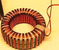
After a lot of experimenting, I converged to certain molypermalloy (MPP) powder toroids that I got luckily via ebay. Their label is A-866142-2 (=Group Arnold part number, see data sheet [576kb], equiv to Magnetics 55866-A2, see data sheet [550kb]), the diameter is 3in (77mm) and AL=142. I found that a single toroid (35 turns ~ 180 uH) doesn't saturate to at least 14A and can easily transfer well beyond 1KW without getting warm. I also experimented with stacks of two and three of such toroids and found them safe well beyond 20A; I am using two chokes, each consisting of two toroids wound together (35 turns giving ca 350uH), which works well at least up to 30A, however I didn't push yet to see where the ultimate limits are.
However, I do not know how to obtain such high power cores in a systematic and reproducible way, other than possibly directly from the manufacturer; in other words I couldn't find a mail order source where one could get such very high power inductors in a simple and affordable way (though it seems that the person I got those toroids from has a lot of more of them, I can give details upon request).
Probably some ETD or other standard cores can be used as well, but I don't have any experience with those.
I made some accurate measurements of the current swing through inductors, and compared this to theoretical computations. The first example, corresponding to a single MPP core A-866142-2 which I am using in the SMPS, fits theory perfectly and shows no sign of saturation. The second corresponds to a single ferrite core of type Amidon FT240-67 (2.4in diameter, material #67, AL=50). It clearly shows an onset of saturation, and demonstrates that the actual peak current becomes quickly much larger than the theoretical value. Such a core is totally unsuited for an SMPS !
On the x-axis we have the output voltage over a 9.2 Ohm load (so the average current is I=Vout/9.2), and on the y-axis the peak current through the inductor (f=33khz, L=180uH, Vin=160V)
Since it is fun and instructive, I have computed various current waveforms through the inductor (see the gzipped Mathematica notebook). One could also just use the interactive web site for doing this and more. Below I added below some typical examples tailored to the usual 100V/10A argon laser needs that may inspire the reader. As long as the inductor does not saturate, one can easily reproduce these diagrams on the oscilloscope (by monitoring the voltage drop over a resistor in series with the "cold" end of the choke).
Current waveform through inductor: the horizontal axis is time in microseconds and the y-axis is the current in A through the inductor. The plots are for Vin=330V, L=180uH and Vout=100V and for average output currents of Iout=4,8,12A, resp. For the left f=100khz and for the right, f=33khz. You see that for the latter case the SMPS is in discontinuous mode at 4A, it thus would create enormous ringing and RF interference. Thus a larger inductance would be advisable, or a higher switching frequency, if you want to run as low as 4A.
Finally some little help for determining the actual inductivity of your SMPS choke if you don't have an LC meter; it works surprisingly accurate, up to a few percent. The idea is to kick off some ringing in a LC circuit and read off the period of the damped waveform off the scope. The setup I was using consisted of the PWM unit of my SMPS, for which I have temporarily slowed down the frequency to something like 1khz, by adding an extra timing capacitor. This gives needle-sharp isolated impulses on the output that normally leads to the mosfet driver IC. Instead these impulses are now fed via a 1pF cap to the resonant LC circuit, consisting of the choke (whose inductivity is to be determined) parallel to a 1nF cap. The ringing waveform is observed on a scope, and the period lenghth (between two subsequent peaks, say) is determined in microseconds. The inductivity can then simply be read off from the following diagram:
On the x-axis there is the inductivity in uH and on the y-axis the period length in microseconds (for C=1nF).