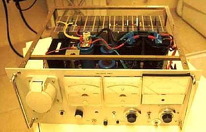
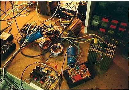
(In these pics, the second mosfet unit was not yet implemented)
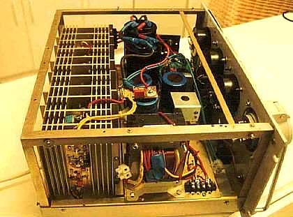
Filament transformer in foreground middle; to the left, mosfet driving circuitry on heat sink. The blue caps are specific low-ESR caps that can do 9A at 10khz each; the black caps in the background are the 2 x 3300uF 50Hz filter caps.
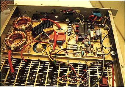
Shunt and bleeder resistors in middle foreground, main filter caps screwed from behind to PCB board in center. Some transistors of my old linear PS are still visible, in the mean time they have been replaced by the second mosfet power module. Mostly shielded cables were used, and the PWM unit was kept as far away as possible from high-current lines; so far no sign of any instability. The fat red cables near the inductors are shielded by copper mesh sleeves to reduce RFI; insulated by shrink tubes.
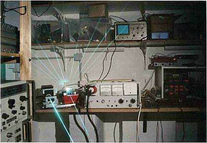
It finally works !
Test setup:
Thank god I wasn't electrocuted ! Now it's rather the eyes that is in danger...