in lower part of pic:
Some explanations referring to the circuit diagram:
The gain control pot can also be replaced by a 100K resistor - I had this for added safetly, ie, for starting at low gain and then tuning up, to see whether oscillations occur (which didn't happen).
The unit connects to the output current control potentiometer, which may be located via a shielded cable at the front panel. The current control feedback is fed from the output stage d) via a suitable sense shunt resistor that needs to be adjusted according to needs; the feedback voltage range the IC wants to see is about 1-5V, so for example 0.5 Ohm gives max current 10A, etc. The resistor dissipates quite some power (50W for the example) and if you don't like this, you may replace it by a Hall sensor like in the Omnichrome PS (but you need then to adapt the voltage range appropriately, eg. via an op-amp). The unit runs at ca 80khz but this may be adjusted (30-200khz, say) by changing R8 and/or C19.
Moreover there is an voltage feedback so that the zero-load idle voltage is not 310V but can be adjusted to several dozens of volts above the laser tube discharge voltage. Otherwise the storage capacitor would be charged to 310V and produce a huge current inrush into the laser tube upon ignition; better only start the tube after having set the idle voltage not too much above the discharge voltage ! Just tune it up slowly until the laser ignites reliably, and then keep the setting.
When running idle, the Mosfet drive pulses are chopped short and this creates a little whining or rattling noise in the inductor (and you see the most entertaining waveforms on your scope ;-); this is caused by the very rapid charging of the filer cap when the output voltage goes below threshold, followed by a "long" break. The peak current through the inductor can be easily several dozens if not a hundred amps (as measured through R3), with duration of a few microseconds - this is nothing to worry about, as long as the safe operating area of the mosfets is not exceeded. Similar effects also happen if the regulator runs in "discontinuous mode", ie, when the current draw is less than ca 3A (depending in the inductivity of the choke and switching frequency).
Instant shutdown can (and probably should) be done by shorting C10 at pin 8; one may want to attach some interlock circuitry here. C10 also determines the soft-start time, which means that while it is charging, the pulse width is gradually increased until the full output voltage (determined by the idle voltage pot R10) is reached. This is very important because otherwise the mosfets could be blown at startup when attempting to charge the main filer cap C12, which effectively looks like a short circuit to them.
In order to further protect the mosfets, and also to prevent the mains fuse to be blown upon startup, I included a soft-start resistor R23 in the AC input line. When switching on the unit, I let it first run via R23 for a second or so for charging the caps, before going to full throttle; it limits the startup inrush current to something like 5A.
It is strongly advised to check current and voltages on the mosfets for all conditions, in particular at power-on, with and without load, and shutdown (at reduced voltage at first, then gradually increasing it).
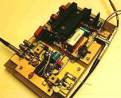
Note that CX4 (center-left in the pic) between the PWM unit and the
isolation unit grounds is crucial for avoiding oscillation !
Note also that practically all capacitor values in the whole SMPS
(apart from the timing cap CX2) are not very critical and could be
changed by a wide margin. Note also there there is no blocking
capacitor in the current feedback loop, ie., parallel to the Zener D7;
any capacitor here introduces severe instability (I have also made a
simplified PSPICE analysis which confirmed this).