Return to home page
After dealing with many versions of analog-driven TEC-Controllers specifically suited for laser diode hologrpahy, I thought it would be time to modernize and find a digital solution. For background, see here. The advantage is of course broad adaptability with regard to PID parameters, easy remote control, protection features, getting rid of potentiometer/trimpot drift, and dual (heating and cooling) drive capability being almost for free, since a bi-directional PWM H-bridge is already close to digital control in the first place.
Moreover today whole Arduino Uno boards are available for about 3 Euro including shipping from China, so almost any other solution would be more expensive. Add to it the easy programmibility and broad range of software for the Arduino, so there are many good reasons to go this way.
To be clear: the primary purpose of this controller is to temperature stabilize laser diodes for holography. This requires stability to about 1/1000 degrees, tied to a specific kind of hardware, for a relatively narrow temperature range. Also, tuning does not need ultrafine steps, it is more important that a given temperature is kept stable for a long time. The intended heat loads involve laser diodes with up to about 500mA drive and mechanically look typically like as shown further below. So explicitly, the controller is not optimized for fine scanning over temperature (like for spectroscopy).
My plan later is to make an update for the LD driver later too, giving another Arduino shield which can be stacked on top. This setup is supposed to be suitable for desktop laser diode controllers with nice controls and LCD display. Moreover a miniature version is planned with less power (1.5A), where both TEC and laser drivers are on one board and a stacked-on Arduino Nano is used for control. This setup is supposed to go into compact laser heads.
So here are the specifications:
- hardware as Arduino Uno Shield, and cheap parts if possible
- full H-bridge for bi-directional TEC drive
- 12V unipolar supply
- up to +/-3A current; intended Peltier sizes about 10x10mm to 20x20mm
- standard 10k Thermistor for sensing
- setpoint range about 10 deg, modifiable by choosing different resistors
- temperature stability < 1/1000 degree for hours
- noise level about 2/10.000 deg
- PWM ripple about 80mV_pp at 50:50 duty cycle
- precision current control/monitoring via dedicated sense circuitry
- configurable current limit (max +/-3A)
- auto turnoff for open/shorted thermistor, temperature out of range, and H-bridge overtemp.
- control via potentiometer incl rasterization for stability
- additional control via USB serial terminal, optionally LabVIEW
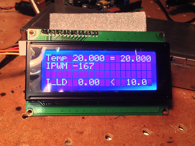
- optional LCD display
- automatic PID control loop configuration
- saving basic operating data in EEPROM
- ready interface for companion laser diode driver
General notes about the hardware design
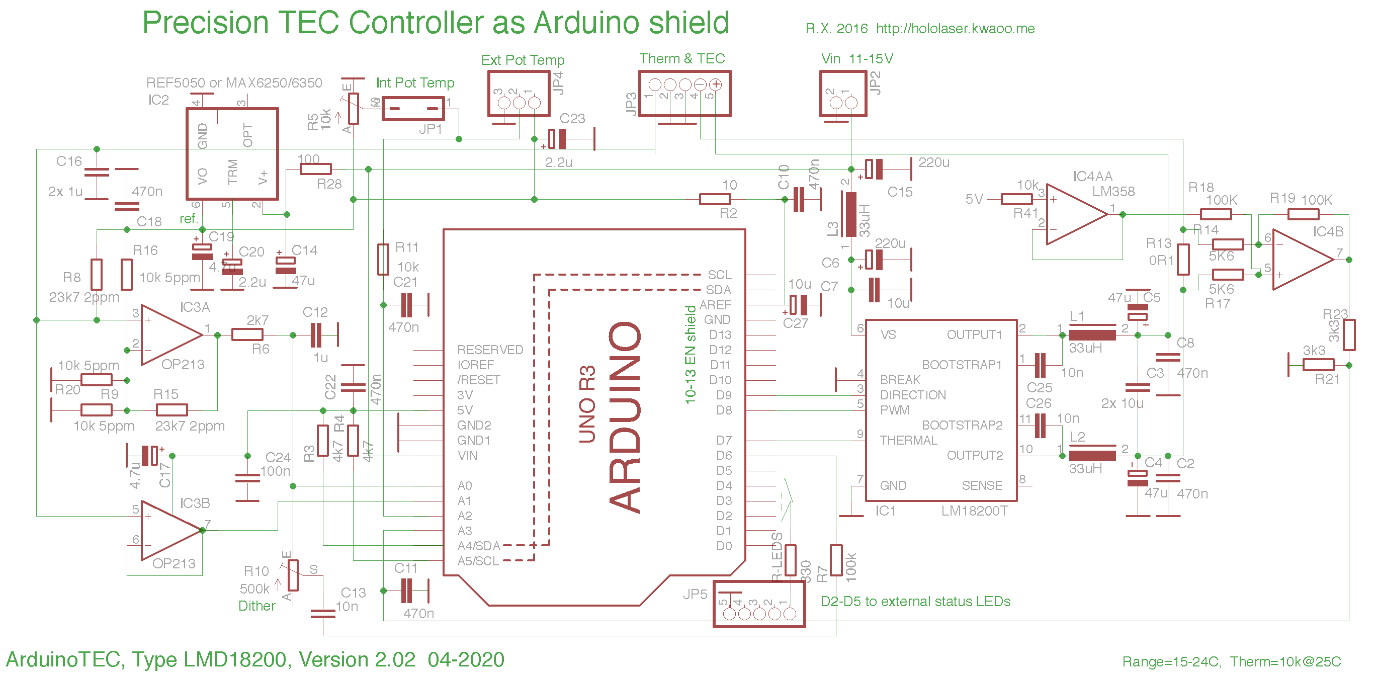
Here the schematics, a higher resolution pdf is linked here (older version 1.1 with simplified current sense):
 >
>
A few comments on the schematics:
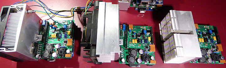
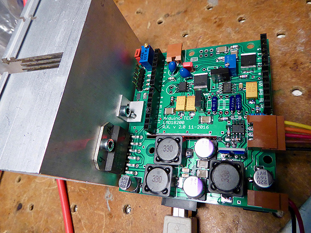
Some more pics::
This shows where the 10u ceramic cap goes directly between the reference and ground terminal of the Atmel processor:
The backside has an uninterrupted ground plane where important, the slit splits the ground into a high power digital and analog part, and helps for thermal decoupling of the heating parts. One can also solder a metal shield along it to fight the strong fields from the PWM controller.
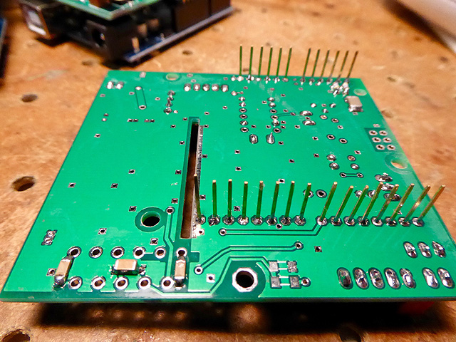
PCB version 2:
![]()

This was my first Arduino project, so surely this is somewhat amateurish.
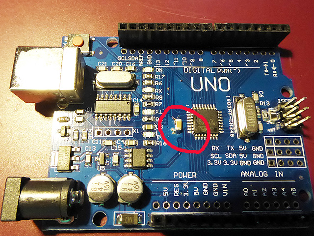
The interesting challenge was how to raise the PWM and ADC resolutions beyond the 8, resp 10 bits, of the Arduino, which do not suffice to achieve the necessary accuracy of the PID control loop; and I wanted to avoid separate I2C chips.
For the PWM output the problem was the following. There are three timers in the Arduino Uno, two with 8 bit and one with 16 bit resolution. The latter would be ok as far as the resolution goes, but it amounts to dividing the 16Mhz clock by 65535 such that the PWM frequency would be less than one khz! This may be fine for motors, but not for the application here: the requirement of low noise requires substantial filtering of the TEC current (the laser diode will most likely be supplied through the same cable as the TEC, and imagine the cross coupling if there are some amps and volts carried alongside!) Substantial filtering involves however gigantic inductors and caps at this frequency: not feasible. Not without reason commercial TEC drivers use PWM signals even to the order of Mhz. So what to do here?
I managed to cook up a software solution that allows to run the PWM controller at the natural speed of 63khz (this corresponds to 8 bit resolution, ie, 255 steps per 62.5nS length), despite having16 bit resolution which has 65535 steps. The idea is as follows. Imagine you want to obtain 128.1 steps output, while you have just 255 steps at your disposal. So it seems you can get only 128 or 129. However, you can send 9 pulses of length 128 plus one with length 129. So in average you get (9*128 + 1*129)/10 = 128.1 steps. Analogously to get finer resolution you may send eg 32767 pulses of length 128 plus one pulse of lentgth 129, and so on. You get the idea: folding more bits into the time domain.
However one may object that this is cheating: by introducing a longer time scale there will be lower frequency components in the output, that are less attenuated by the LC lowpass filter. Indeed so, an extreme case is for example where you want to get 0.1 steps output, meaning that to send 9 zero steps output and one with step 1, which means that effectively you have lowered the frequency by a factor of 10.
This is not problem for the application here, since the duty cycle will be mostly concentrated near 50:50, especially in equilibrium conditions (eg a duty cycle of 1:9 would correspond to a PWM voltage output of about 0.9*12V which would mean more than 10Amps on a small TEC, so this will never occur for our applications). On the other hand, for a near 50:50 duty cycle (like 9* 128 plus 1* 129 steps out of 255) the spectral contribution of lower frequency components is minimal. So in practice there is no issue to deal with, but it should be clear that there will be more noise flying around at higher PWM currents; but this is typically during a warmup/cooldown phase where noise is anyway of no interest.
To implement this I couldn't use the usual pre-fabricated timer libraries but had to figure it out by myself using interrupts, which was instructive for me novice. For details see the code.
For the input ADC of the ATmega168/328 the problem could also be solved by folding more bits in the time domain, a well-known technique called oversampling. This is more than just averaging. How does it work? The natural resolution of the Arduino is 10 bits which amounts to 1023 steps. Assume you got a stable signal of 512.1 steps. Each measurement will yield 512 and averaging hundred times continues to give 512. The point is that superimposing a triangular waveform of a suitable frequency and amplitude will shift the values around, while cancelling itself out upon averaging (suitable white noise can also do). In this way values in between of 512 and 513 can be sampled. This is called dithering.
In our setup, Timer 0 of the Arduino is used to generate a triangular waveform at 490Hz which is fed together with the signal of the preamp to the input pin A0. The trimpot R10 above needs to be adjusted such as the triangular waveform across the input pin is about 10mV_pp. We use 4^N= 256-fold oversampling where N=4 gives the increase of resolution. So in other words, we obtain 14 instead of 10 bits ADC resolution. Thus turns out to be sufficient. Taking more oversampling starts to take too much time for the loop process of the microcontroller and so interferes with I/O and other stuff.
I also found that there can be periodic noise peaks (timescale in order of minutes), which is likely an interference effect, eg caused by almost commensurate timings of data I/O. The resolution was to shift the actual measurement moment within the 100msec window of the controller PID loop by a small amount in a random manner. Then all these periodic patterns average out into the noise.
You can imagine that to figure all of this out took quite a number of hobby evenings ;-) Apart from building the hardware....
Now here some other points of the software:
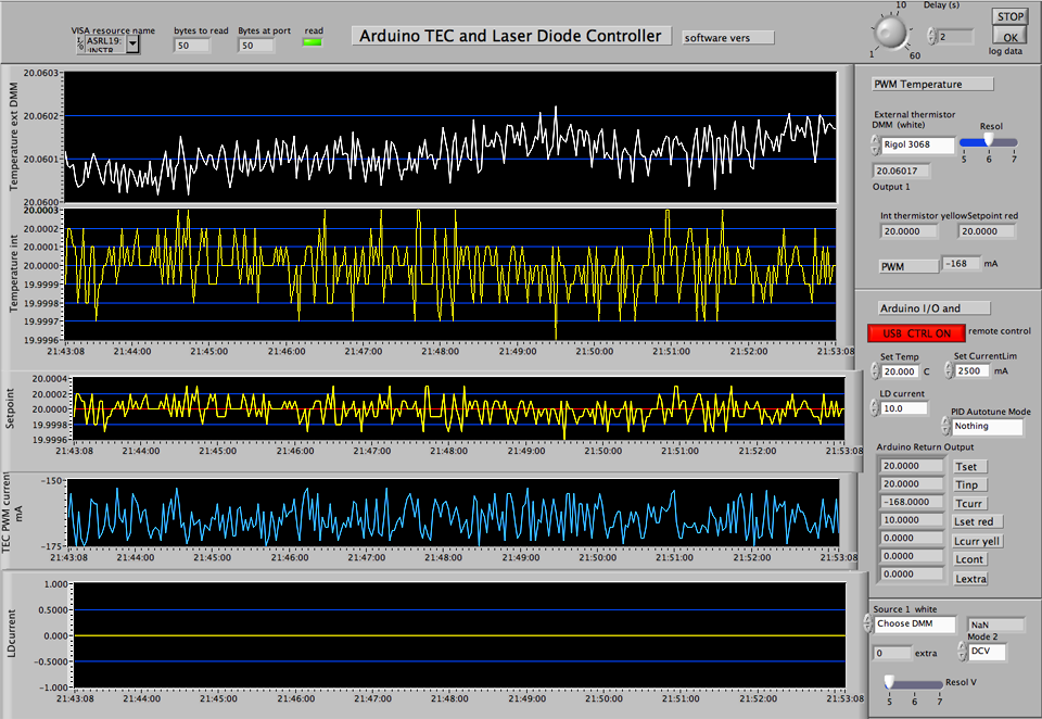
Here my primary LabVIEW interface via USB; shown is from the top: independent temperature measurememt via second themistor and Rigol DM 3068 DMM (white); temperature as seen from the Arduino (yellow); dito compared to setpoint (yellow/red); TEC current (blue). Note that the temperature fluctuations are about 0.1mK_pp:
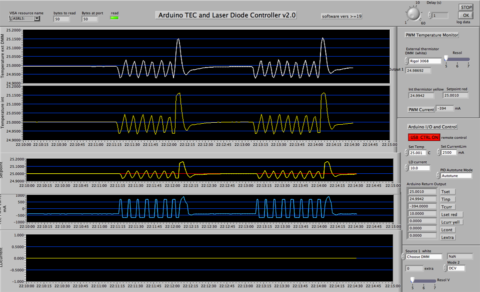
This shows PID autotune mode where one sees the test signal (blue) and response (white, yellow):
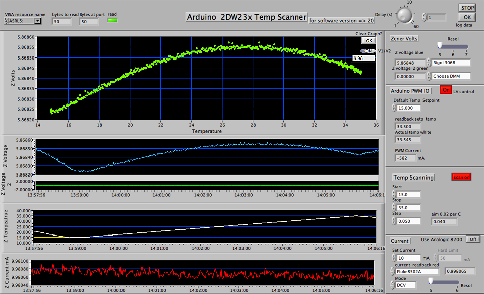
Here an application for something else than a laser diode: temperature scanning of a 2DW232 Zener diode at fixed current to determine its zero temperature coefficient point (here at 27C due to a resistor divider):
Most of the time I spent with temperature stability meaurements, which by their nature can be tedious. Often I ran tests over several days. Here is a collection of recent results I obtained with the latest, version 2.0 board. All are at fairly constant ambient temperarure, about 17 +/- 0.2 degrees.
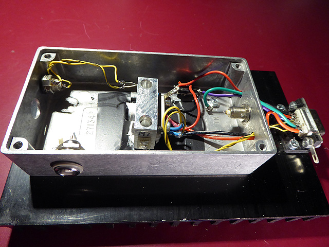
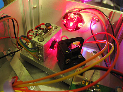
The followimg refers to a small thermal load, a free running laser diode in a 20x30x15mm alu mount shown in the center here, atop a 15x15mm type 1703 peltier:
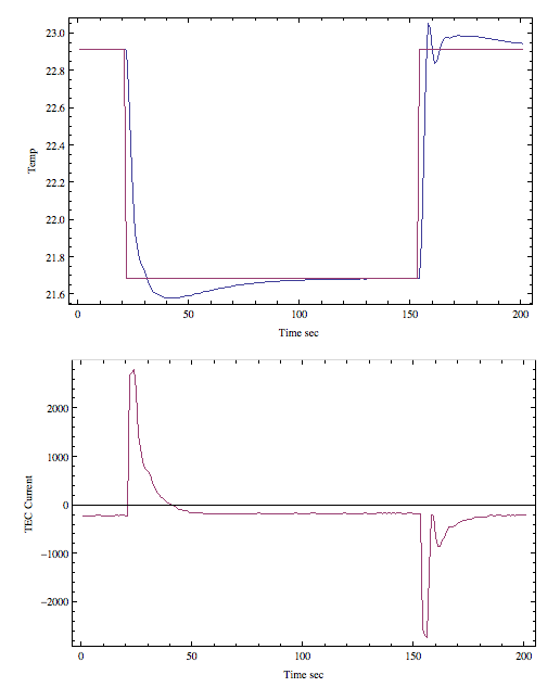
Shown below is the response of a temperature setpoint change: the red curce shows the setpoint, the blue the actual temperature and below the red the TEC current:
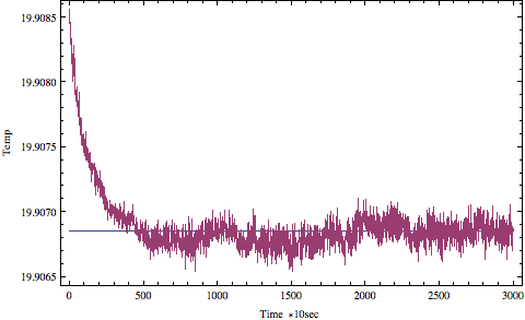
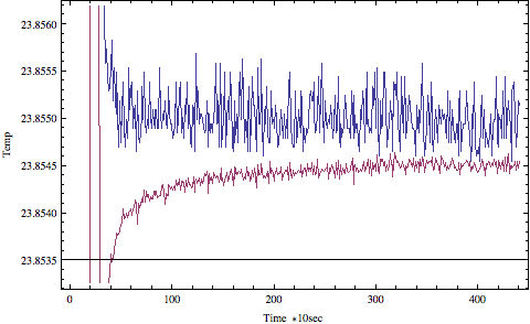
Turn-On behavoir. You see that after approx 1.5hours, there is practically no drift, it is less than 0.0005 degrees over 7 hours:
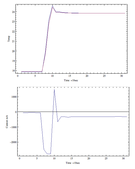
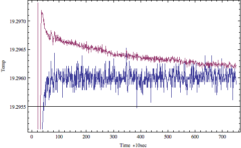
Step response after a change from 20 to 15 degrees:
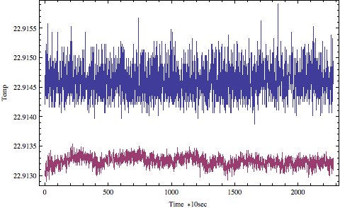
Long term stability in constant ambient conditions. The red curve shows a measurement of an independent thermistor connected to a 6.5 digit Rigol DM3068 DMM (like above). The blue curve shows the measurement as seen from the Arduino via the feedback thermistor. It is much more noisy due to hardware limitations. But what counts is the actual temperature which is better represented by the higher precision red curve. The noise is about 0.1 mK RMS over about 6h:
Here something mysterious, and I wish to understand it better: there is some mention in the literature that if the temperature difference across the Peltier is small, the control is less stable; see eg., here. I didn't get a clear picture, though, I just noticed a general increase of noise towards higher ambient temperature (or rather Peltier heat sink temp), rather than a peak at the ambient temperature. Below a compilation of a dozen or so measurements of the RMS noise as a function of the setpoint temperature; the ambient temperature was constant 18 degrees:

The following measurements are from an ECDL head which a considerable thermal load, namely diode mount plus grating on alu base plate:
Since the thermal mass is larger, noise is smaller and and also all responses slower. As above, the blue lines show the temperarure measurement by the Arduino, the red the measurement by an independent thermistor and DMM.
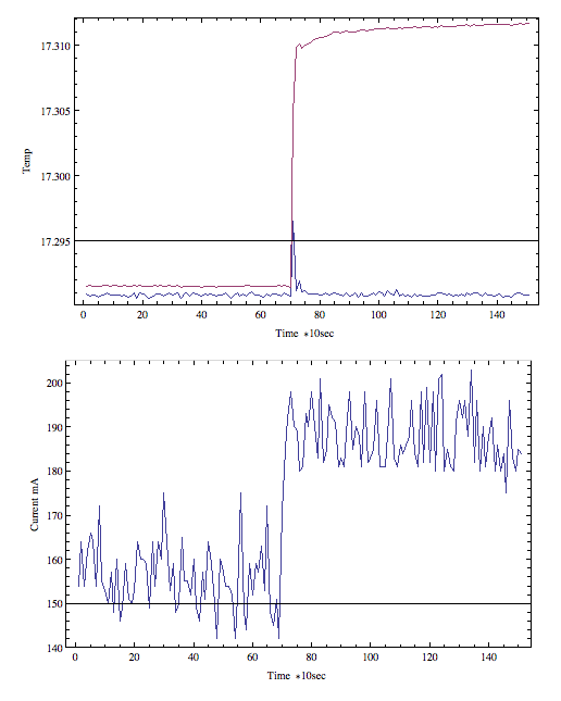
Step response for temperature jump of about 6 degrees:
Zoomed version:
Jump back to 19 degrees:
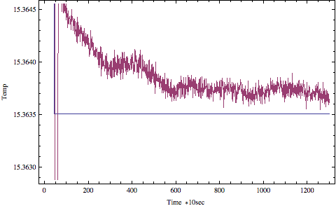
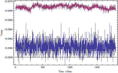
Long term stability is excellent, noise is about 0.1mK_pp or 0.04mKrms (=standard dev):
Here the effect of stepping the laser diode current up from 125 to 175mA; one clearly sees that the Ardunino (blue curve) well regulates back, but the actual temperature near the diode (red line) differs - due to minute temperature gradients between the two thermistors. In the second plot the Peltier current is shown:
Some more measurements, in particular drift against ambient temperature changes, are planned for the future.
Here is the current Arduino software (v20), incl libraries that are needed. No warranty whatsoever is implied. There is also some LabVIEW software for interfacing, incl demos which are not functional because they need device drivers that reflect my local hardware. They are included as demo to see how the interface vi's can be used.
Current: Vers. 1.2 -Jan 18/2017
Changes:Vers. 1.1 - Jan 18/2017 minor corr
Vers. 1.0 - initial
Return to home page