Return to home page
0.1-10Hz Low Noise (200nVpp) Amplifier, 80dB
0.1-100Khz Low Noise Amplifier, 80dB
Low Noise 10V Voltage Reference, 1.7uVpp for 0.1-10Hz
Ultra Low Noise Zener Diode 2DW23x, <0.3uVpp for 0.1-10Hz
This is a slowly ongoing project that ties together various kind of interesting electronics. The issue is to create a voltage/current reference with lowest practically possible noise. This is motivated in part by a long term project to develep a cheap, stable and low noise current driver for laser diodes (to complement my Arduino based TEC controller).
It is also motivated in part by the discussions at eevblog on the chinese super-low noise Zener diodes 2DW23x. This is kind of a sweet electronics challenge and so I got quite a few of those to play around and see. My findings will be added incrementally at the end.
In order to address questions of noise necessitates suitable low-noise amplifiers, an interesting exercise in itself. For this the following threads were extremely helpful: DIY low frequency noise meter and some measurement result of voltage references and Einfacher Messverstärker 10 Hz - 100 KHz. I won't add a lot of new info except my particular comments and measurements.
0.1-10Hz Low Noise (200nVpp) Amplifier, 80dB
The tips in the DIY low frequency noise meter thread were extremely valuable, in particular the issue of leakage current of the input capacitor. I never thought that this could be handled with hobbyist means. But indeed checking out a few caps I had around, there were some with minimal leakage current, so this was fine! It comes down to less than 0.5nA after enough settling time. Practically, I attached a bank of capacitors in series with 1MOhm each to a 12V source, and waited a day or so. One nA translates to 1mV drop acroess the resistors, which is easy to check.
Still, building such amplifiers is a slightly tricky business. Here is the schematics incl LTspice simulation:

Comments:
1) Not shown are protection diodes, as well as a simply LM358 circuit that provides a virtual ground, ie +/-2.1V dual supply from a single 4.2V battery.
2) R5 is two 2k7 low noise, bulk metal foil resistors in series.
3) C4 restricts the upper bandwidth to 10Hz. If taken out per switch, bandwidth is 100Hz.
4) Contrary expectations, when taking both opamps of the ADA4528-2 in parallel, the noise increased rather than reduced by a factor of 1.41. So I use just one.
5) Shielding: an aluminum case with slots on the sides didn't work at all due to overwhelming 50Hz noise. One really needs a kind of watertight shielding, I used a classic Teko case intended for RF applications. Actually two nested ones, the outer one holds the 4.2V LiIon battery and a 50:50 opamp voltage splitter for generating a virtual ground.
6) Ground loops. In order to get below 1uV or so baseline noise, extreme care needs to be paid to proper grounding. At first I used my practice with RF circuits and just mounted input and output coaxial connectors within the walls of the Teco case. But that still left some 50Hz noise, the few cm distance between the connectors still picked it up! What actually helped was to mount both connectors isolated from ground, and define a star point next to the input of the opamp, and link the shields of the connectors only to this single point. Then this noise disappeared.
However, even by using a battery for the amplifier, one is more or less guaranteed to get ground loops when measuring references in existing other circuitry, especially if the scope is grounded. Part of the solution was to put between amp and scope an extra isolation amp. I use an AD210AN which I had at hand, and I also added an extra gain factor of 10, so the total gain is 10^5. This means 1uV AC input will come to 100mV output.
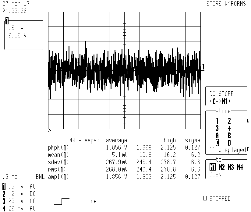
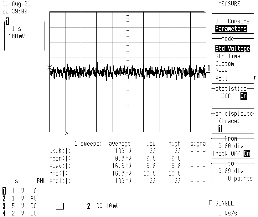
The picure below shows the 200nVpp base noise level:
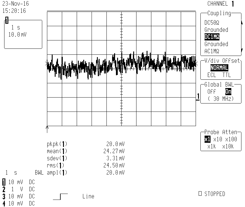
Note that the 3.3mVsdev translates back to 330uVrms at the amplifier output, which is almost double of the value (188uVrms) computed by the LTspice simulation. But there are so many factors and uncertainties going into this so I am happy with it as it is.
7) The frequency response was checked via a function generator via a 1M/10Ohm divider and pretty much as computed.
8) I switched to Teflon cables for the input. For ordinary RG174 style coaxial cables the slightest, barely noticeable movement induces noise. Also good connectors with gold contacts are important.
9) To maintain the formation of the input capacitor, I keep it under constant voltage all the times (for standby 9V batt with 4.7V Zener and 100k in series, it draws less than 1nA).
0.1-100Khz Low Noise Amplifier, 80dB
The previous amplifier covers up to an upper bandwidth of 10Hz or 100Hz, selectable per switch. Here now a companion that covers from there to 100khz. Part of the motivation is to quantify a weak PWM signal in a laser diode driver output.
The design was inspired by the thread Einfacher Messverstärker 10 Hz - 100 KHz at microcontroller.net (in german).
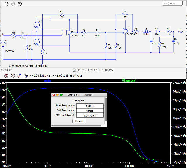
Here is the schematics and LTspice simulation:
Similar remarks as before apply - protection diodes are not shown, etc. Extra remarks:
1) First I used an AD797 opamp for the front end, very cheaply bought via Aliexpress. It was a fake, having huge noise and a bandwidth barely more than 20khz.
2) The LT1028 is excellent for low impedance sources which is the case for my applications. It has a notorious noise peak around 400khz which is the reason for the extra filtering around L1.
3) R5 is a parallel pair of bulk metal foil resistors, but the influence on the overall noise is not large anyway.
4) R3 is used to fine-tune the overall gain to 10000.
5) R8 represents the input resistance of the scope.
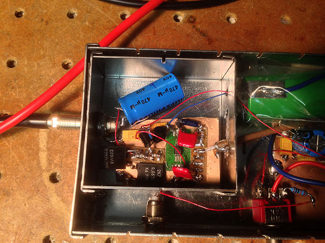
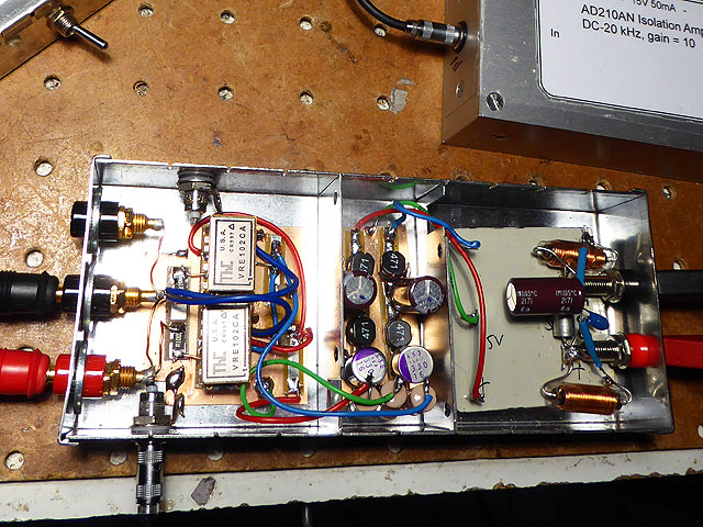
6) The previous remarks concerning shielding, ground loops, and star points apply here too. In the pic below, note the direct connection wire between the shields of the input and output connectors - connecting them directly to the case without isolation induces 50Hz and higher frequency noise. The star point is right below the input connector on the right:

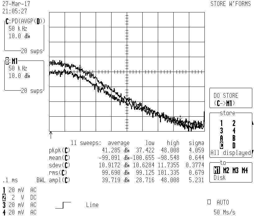
7) The picture shown below is the noise frequency response up to 500khz, which follows the gain curve. The upper trace is for open input, the lower trace is for a terminating input resistor of 50Ohms. Clearly seen is the drop of noise for low input impedance.
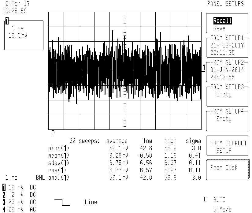
8) Noise in the time domain: the measured 7mVrms is about twice the value computed in LTspice (3mVrms). Translated to the input it amounts to 0.7uVrms/5uVpp wideband noise (0.1-100khz).
Low Noise 10V Voltage Reference, 1.7uVpp for 0.1-10Hz
I happened to salvage from trash a dozen or so precision voltage references VRE102CA. Selecting them for noise and combining two of them in parallel (via 0.1Ohm resistors), yields a voltage source of exceptional low noise and, hopefully, stability. Indeed, being used they should have seen some good burn-in time. In comparison to my new Rigol 3068 the reference is off by almost exactly 1mV, which is just within specs. I hope to get a more precise number from my employer's cal lab at some point. In the meantime it is powered up 24/7.
1) Slightly worrisome was to provide the +/- 15V supply via batteries. I opted for an built-in, isolating DC/DC converter, while paying attention to thorough filtering and shielding. Despite efforts and multiple LC filters and extra mu-metal shielding, there is still some weak 35khz or so signal from the converter seen in the output. Well, I'll leave it like that.
2) Planned is a connection to an internal thermistor, located on one of the chips, to care for reproducible temperature conditions.
3) I paid attention to EMF by using copper wires, gold-plated brass banana sockets (some cheap ones via Aliexpress where fakes), and low-EMF cadmium solder for the critical output wiring. So far there is almost no drift seen at 6.5digit resolution.
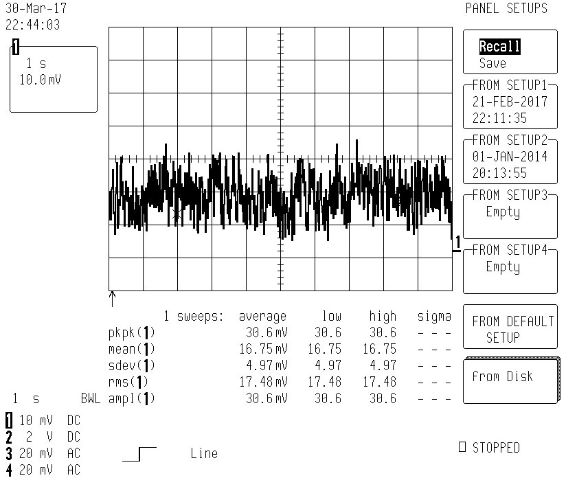
4) I selected among the chips the ones with lowest noise, which is about 1/2 of the typical value of 6uVpp. In total, after taking two in parallel, the resulting noise is less than 1.7uVpp for 0.1-10Hz:
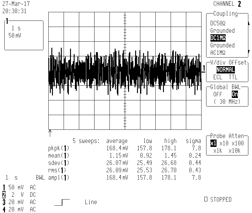
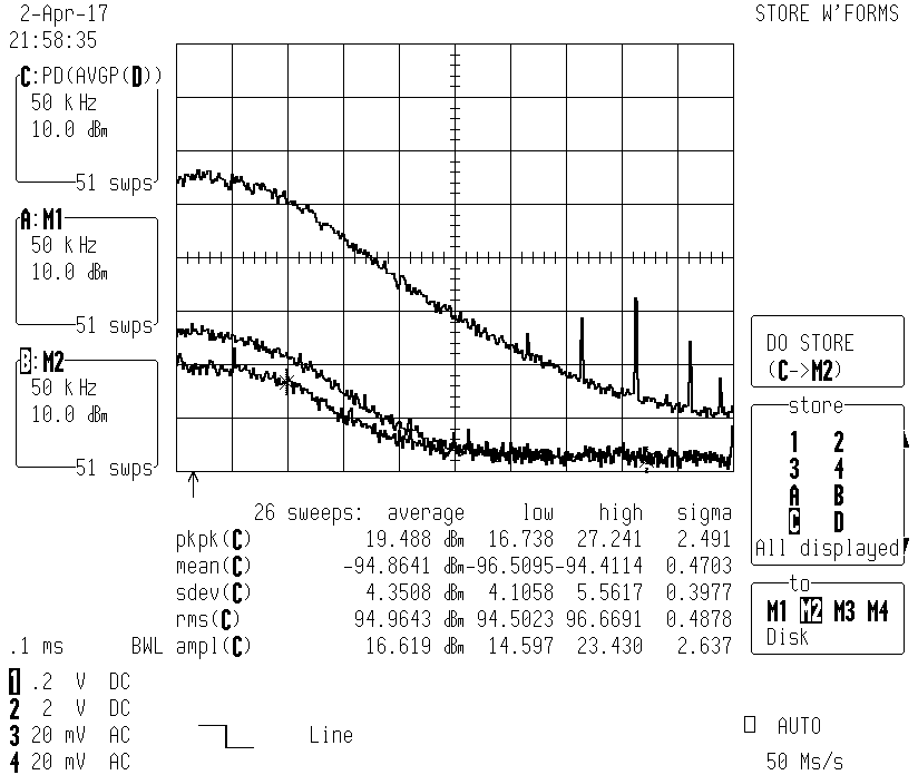
For 100khz bandwidth, the noise is much higher, about 19uVpp or 2.7uVrms:
In the frequency domain the noise reflects the response of the amplifier which cuts off at about 100khz. At high frequencies there are spurious signals from the environment. The lower traces show the noise of the amplifier alone, with and without a 50Ohm resistor:
Ultra Low Noise Zener Diode 2DW23x, <0.3uVpp for 0.1-10Hz
![]()
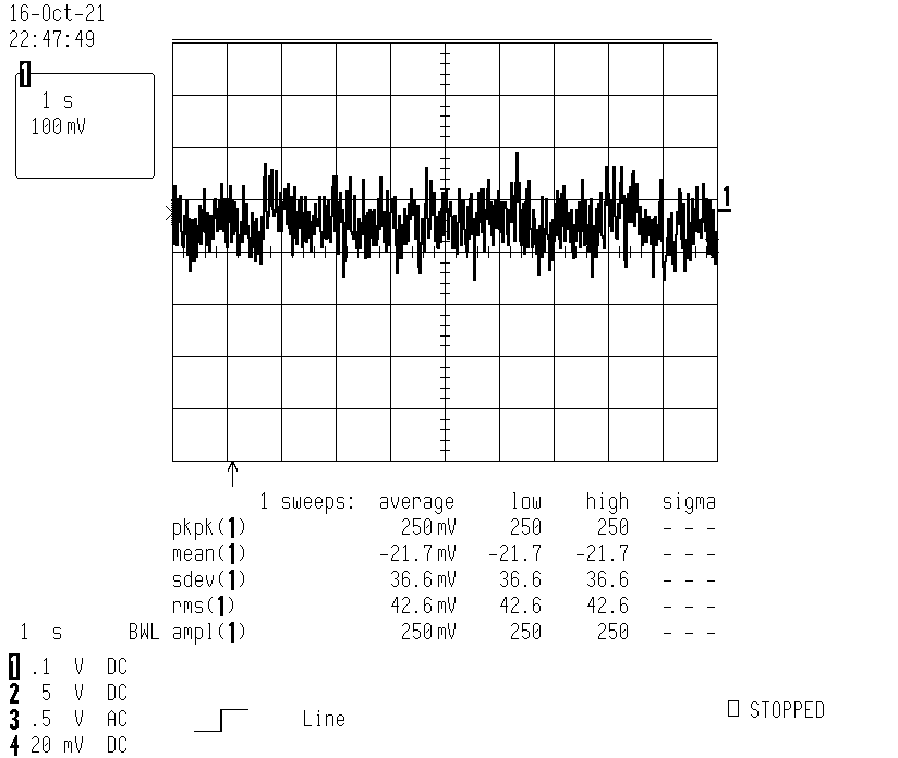
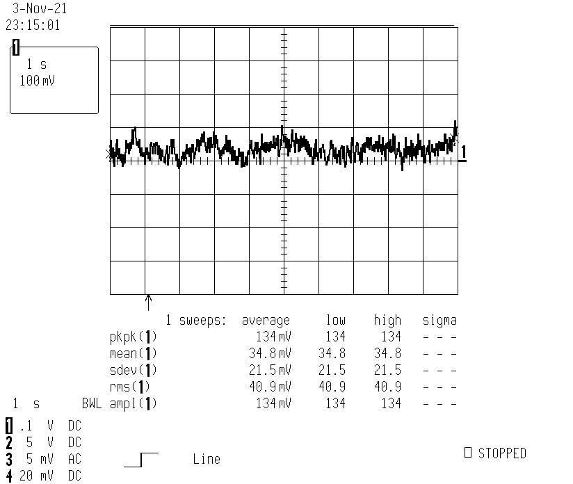
Noise of 300nVpp at 0.1-10Hz bandwidth:
A circuit using this diode as reference is under development. For general remarks about this diode, see here.
Some checks of Voltage References (5V, at 0.1-10Hz bandwidth)
genuine Maxim MAX6250: 2.5uVpp
fake MAX6250 from Aliexpress/YIXUANTAI 2: 7.3uV/pp

genuine Maxim MAX6350: 1uV/pp (too good??)
fake MAX6350 from Aliexpress/SZYMXD Store: 8uV/pp
apparently genuine LTC6655 from Aliexpress/POCCIO Official Store (supply 5.6V): 2.3uV/pp

genuine Linear LTC665LN (low noise version, supply 5.6V): 1.3uV/pp
Current: Vers. 0.2 Nov 6, 2021
Return to home page