Return to home page
Return to exposures page
The monolithic (single chip) sensors mentioned in the interactive exposures page combine a photodiode with an integrated transimpedance amplifier, and give an output voltage that is highly linear with the illumination over a wide range. Their sensitivity is just right for the intensities typically used in holography. They thus provide an inexpensive and simple way to build photometers for holography with sufficient accuracy. Even without extra calibration, the a priori accuracy should be sufficient for holography applications.
For the TI and Taos sensors TSL25x and TSL25xR, all that it takes is to connect the sensor to a 5V power supply (eg, a simple 3-leg 5V regulator) and to a voltmeter. The accuracy for the R-series is supposedly 25%, which is borderline adequate for holography (50% for the non-R series). Note that TSL250R is the most sensitive sensor and thus best suitable for low power lasers and/or sensitive emulsions, while the TSL251R (and even more so TSL252R) is better suitable for higher power lasers and/or less sensitive film emulsions.
Advantages: cheap, easy to get and to set up.
Disadvantages: small built-in lens requires precise aiming, and does not even
out small scale fluctuations (so you get a jumpy mV reading).
For the Burr-Brown OPT101, OPT202 and OPT301M (the first one is available as free sample from TI, the others are sometimes available on ebay), the accuracy is suggested to be in the order of a few percents typically, and the sensitivity can be adjusted by an external resistor (the plots apply when using the internal 1 Megaohm resistor). For most purposes, these light sensors have similar data and are more or less equivalent - except that the OPT101 suffers from a typical 7.5mV dark voltage, which may be bothering at low light levels (it needs to be subtracted before computing light ratios). The OPT202, OPT209, OPT301M have virtually zero dark voltage, but require an additional negative voltage source to operate.
Advantages: the larger sensitive area gives a smoother reading.
Disadvantages: for OPT202,
OPT301M, a dual,
means positive plus negative voltage supply is necessary. The OPT101
can be used with a single voltage supply, but it has a higher dark voltage.
The following describes a simple circuit using the photosensors OPT101 and OPT202, OPT209. I designed the printed circuit board such as to host all these types, for both the packages styles, "P"=8-DIP and "W"=5-SIP. There are several versions possible, in particular a fully featured version using the OPT202/9 plus a negative voltage generator (involving a LTC/MAX1044/ICL7660 charge pump IC), and a simpler version using the OPT101 without negative voltage generator (which has a higher dark voltage). The corresponding circuits are explained in the schematics, and one needs to assemble the PCB accordingly (for the OPT101 one needs to put an extra solder bridge to connect the ground pin).
Moreover there is a trim pot in order to calibrate the light sensor against some external device. The role of the 240KOhm resistor in series to the on-chip 1MOhm resistor is to boost the gain a bit, and the trim pot is then used to reduce the gain to adjust the sensitivity to precisely match the nominal value as listed in the data sheet, which corresponds to 1MOhm feedback resistance. If one has no light meter to compare to, the trim pot should be omitted or left full open, while the 240KOhm resistor should be shorted such as to have 1MOhm feedback resistance in total. The sensitivity should then still be moderately close to the nominal sensitivity as advertized in the data sheet (within say 20%, see below for explicit numbers).
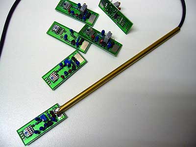
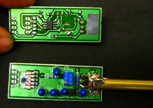
The PCB layout is in Eagle format. The uncovered area to the right is meant to be soldered to a brass tube or similar, to serve as a holder. Here are some close-up pictures that show how things look when assembled:
 >
>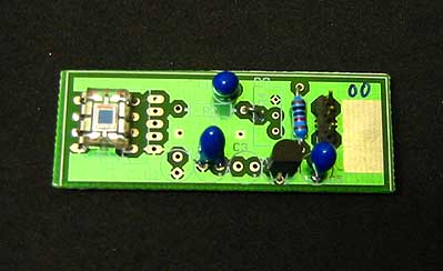
To the left: the fully featured version with OPT202W and negative voltage generator.
To the right: the minimal version with OPT101P and no adjustment pot.
How to set it up: Attach a suitable holder, like a 10 inch brass tube, by soldering (or otherwise fixing) it to the solder area to the right of the board. Ideally use a 3-wire cable and run it through the brass tube, as shown above. Connect power (5-24V) to the pin marked "+" and the middle (ground) pin, making sure of the correct polarity. Connect the positive wire of a digital voltmeter to the third (output) pin and the minus wire to the middle pin as well (there can't be any damage in case you confuse the output with the "+" pin, as long as the polarity is right: the middle pin must be minus).
Here are typical data and measurement values, gathered from more than 20 samples:
Electrical Data:
Supply voltage: 5-24V
Supply current: 1.7mA max, ca 1mA at darkness
Max output voltage: 4.3V (ca 2.7V when calibrated)
Dark voltage: < 1mV (8mV for OPT101 version)
AC noise level (<10Mhz): <0.5mV eff
Output impedance: ca 10kOhm
Recommended load resistance: >1MOhm
Optical Data:
Usable irradiance range at 532nm: ca 1-180 uW/cm^2
Nominal sensitivity at 532nm, as claimed per data sheet (and to which I calibrate the sensors): 15 mV(/uW/cm^2)
Measured uncalibrated, raw sensitivity with internal 1MOhm feedback: 19-22 mV(/uW/cm^2)
Measured sensitivity for other common laser lines,
for sensors calibrated to the nominal sensitivity of 15 mV(/uW/cm^2) at 532nm:
| Wavelength | 488nm |
514nm |
532nm |
633nm |
655nm |
| Sensitivity in units of mV/(uW/cm^2): |
12-13 |
14 |
15 |
20-21 |
22-23 |
Notes:
Return to home page
Return to exposures page
Vers 1.7 10/05