
Return to home page
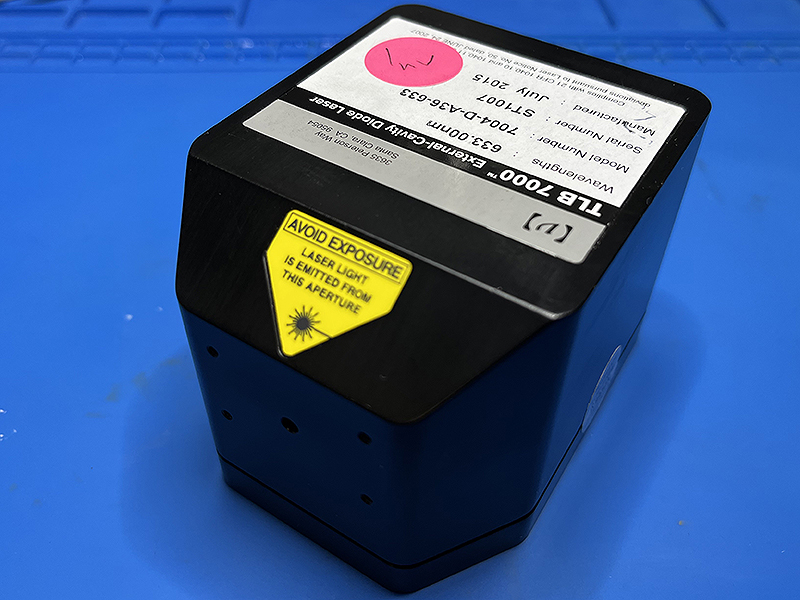
I had gratefully received another nice surplus laser from G.S.: a Vortex TLB 7004-D-A36-633 ECDL. See here for the characterization of such lasers. Their main features include wide tunabilty, small line width and supreme stability, optimized for atomic physics applications.
That's why their cavity design is based on the Littman-Metcalf setup, which ensures a wide tuning range without mode jumps. The feedback beam passes twice the grating and so enjoys higher wavelength selectivity. But the maximal output power is reduced as there is another, wasted beam generated. The main beam is reflected at very small but fixed grazing angle, so that the output beam position is unchanged when turning the extra mirror (pic taken from that ref):

The actual tuning is accomplished by a piezo element, which minimally turns the mirror assembly around a "pivot" point. The whole construction is very intricate, as the pivot point needs to be precisely located up to a few micrometers, in order that the optical path length of the cavity does not change when tuning.
The laser was specified at 10-15mW at 633nm, but the diode was broken. So I had to replace the diode. In view of the high precision technological masterpiece, I had a strong sense of vandalism by doing so, but the alternative would have been to throw it away. Clearly, getting anywhere near the original specs for tuning, stability and sidemode suppression was out of question; not without reason special, AR coated diodes are used by the manufacturer, and this works for low powers only. So a more realistic aim was to use a standard red laser diode and see how well the ECDL could be converted to a laser useful at least for amateur holography.
Even that was way more painful than anticipated. It took a couple of weeks. Here's the story!
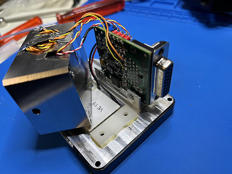
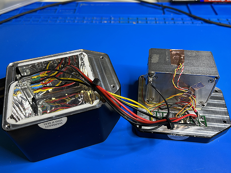
First a sequence of pictures, starting with the closed and opened case. We see a small electronics board and the compact laser assembly made of steel, which is mounted on top a TEC element:
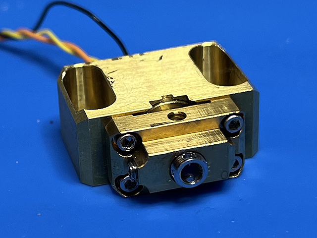
Below we show close-ups of the well-sealed laser assembly, top and bottom parts.
The top contains the diode mount incl collimator aimed at the grating, a temperature sensor and a tiny retro-reflecting rooftop prism as feedback mirror. It can be rotated via a little turning bar leading to the bottom side. Click the pictures for enlargement:

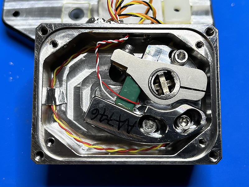
On the bottom side there is the intricate actuator mechanics for rotating the prism around the proper pivot point, realized with an ultra-precise, highly stable, and vibration damped design. The piezo element is the green part. For now we won't need this, though it's a pity.
After unmounting the diode assembly, it turned that the diode had a 9mm case. Thoroughly glued in, it took some pains to remove it. Fortunately I found a 5.6mm to 9mm adapter ring, also shown below:
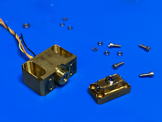
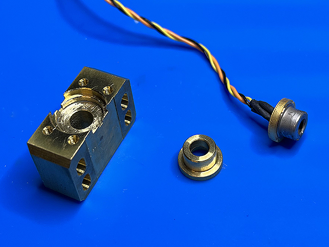
So at first I press-fitted into the adapter a Sharp GH0631IA2GC diode, glued and pressed that into the mount, and then attached the collimator again, all a bit finicky:
After putting it back into the assembly, how then adjust the whole thing? This was and still is a major headache. There are no fine-threaded screws to turn. The degrees of freedom are the following (apart from polarization and collimation of the diode):
First, adjusting the laser mount such that the beam hits nicely the grating in the center; just as a guess.
Second, adjusting the height of the retro-reflecting prism. Fortunately, due to its auto-retroreflecting property, there is no angle to be adjusted, just the height the backreflected beam on the grating (to overlap the primary beam). What I found surprising is that the relevant part of the reflection comes from the sharp 90 degree corner of the prism, which is all the opposite of a smooth cavity mirror! A screw (UNF 0-80,1/2") inserted into the tiny brass thread next to the prism helped here.
Third, turning the retro-reflecting prism by manually rotating the actuator on the bottom side (after the 3 screws are temporarily loosened). The sweet spot is very narrow which doesn't help either. Doing all this by hand seems very crude and surely is neither optimal nor reproducible. I wonder how this is done in the factory!
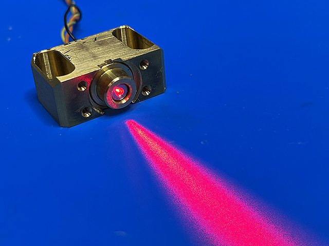
After gluing a thermistor for use with my digital diode laser controller, the assembly looks like this when in operation:

The whole thing was then packed back into the fantastically well thermally isolated, hermetically sealed case that also sports an AR coated output window. The PCB was removed as having no use anymore, its place being filled by the wirings:
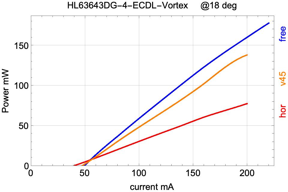
The first measurements were disappointing. With vertical polarization, the feedback was too weak so the diode tended to jump to its intrinsic cavity modes. The lasing threshold current at about 50mA was not recognizably reduced as compared to the free running diode. After again unmounting all, ungluing and regluing the diode for horizontal polarization, plus new adjustments: the power dropped to 50% and the laser was still not reliably running single mode. Typically several external modes lased so the feedback seemed too strong.
Since the Sharp diodes typically don't work as well as the .../.../Opnext/Ushio diodes, next thing was to try a HL63643DG. Bad surprise: the diode die was a fraction of a mm more inside the TO-56 can, and as a consequence the beam couldn't be collimated any more! The obstacle was the adapter ring which protruded about a mm beyond the laser diode window. The lens has a very short focal length and couldn't be moved close enough to the die. So what to do. I tried to mill the adapter shorter by 1/2mm, protecting the diode window with First Contact polymer (my favorite optics cleaner/protector). But the diode window was too small to get rid off all the polymer afterwards, and in the end the diode was destroyed.
So, take another HL63643DG, press it into another adapter ring after having milled that shorter. Now collimation was possible. First attempt, vertical polarization: same fail as before, feedback too weak. Second try, horizontal polarization: superficially much better but power dropped almost by half again, to about 75mW at 180mA. That's an unfortunate feature of the horizontal polarization, further aggravated by the Littman-Metcalf configuration:
Below there are some plots of linewidth (as measured by the CCD spectrum analyzer), plus power and noise.
The first refers to where the backcoupling was strongest, lowering the lasing threshold from approx. 50mA (for the free running diode, 18C) to 40mA:
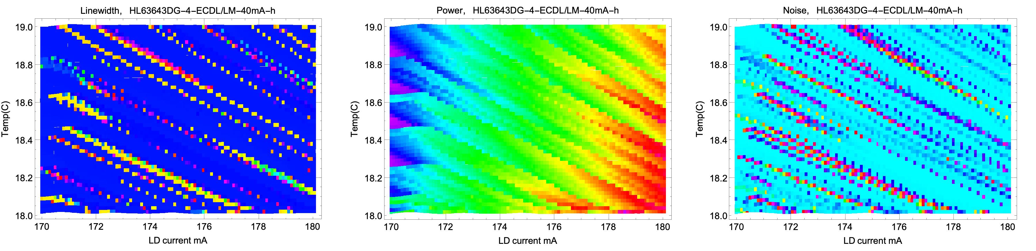
Despite this looks good at first sight,
the output wasn't clean and often there were multimode regions that are not easily seen by the CCD spectrum analyzer. A rough indication of this are the extended noisy zones.
This expectation was verified with a SFPI. A contributing factor may be the large length of the cavity: the distance laser diode-grating-prism is about 3.5cm, so the extended cavity modes lie denser and thus can get excited simultaneously more easily than for a shorter cavity.
For the same reason they are harder to detect too.
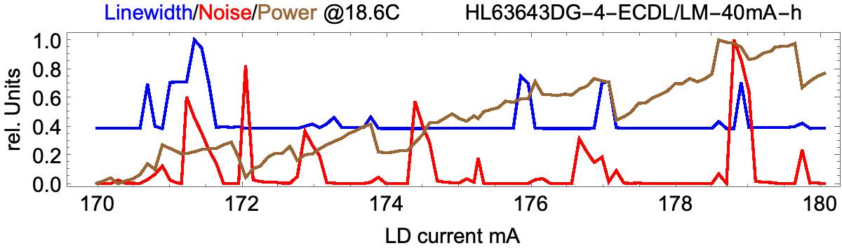
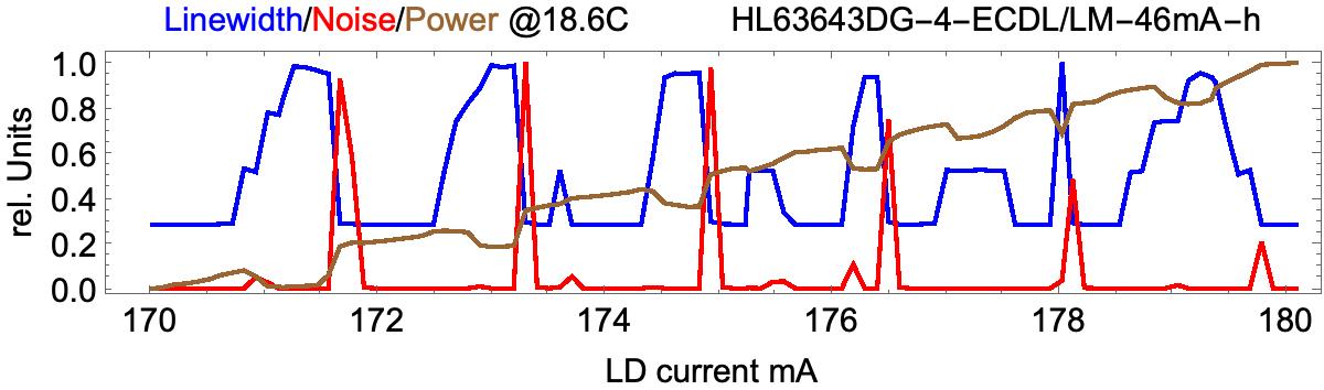
For a different perspective, here is a slice at 18.6C which superficially looks good from the CCD analyzer. But the noise and little power fluctuations in the gaps indicate that mode spectrum is indeed not clean:
Here another shot at it, where the collimation has been changed to weaker backcoupling so that the lasing threshold raised to 46mA. This looks worse but is actually better:
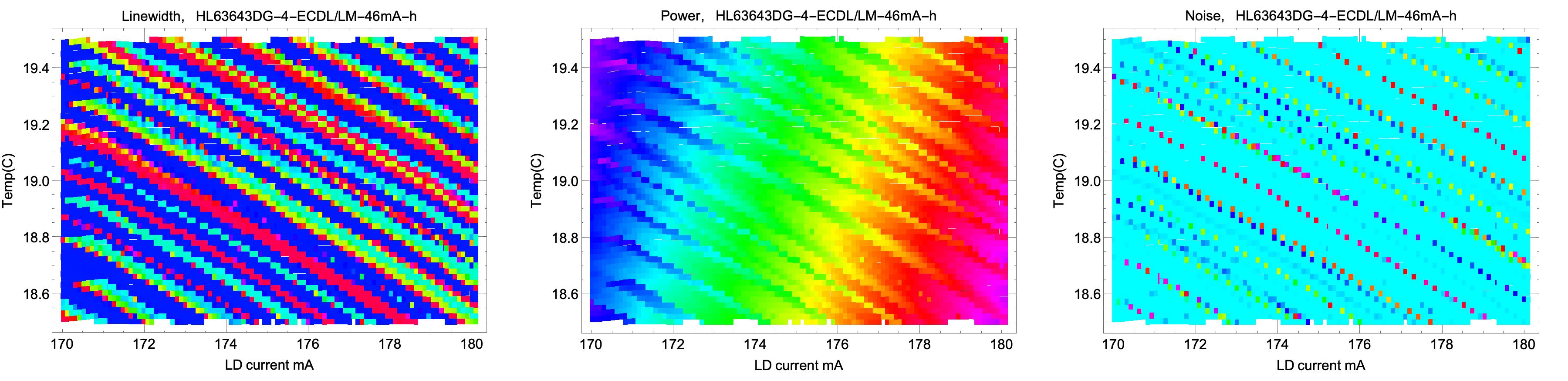 That is, while the zones of apparent single mode operation are smaller as compared to above, the spectrum is in fact mostly true single mode
there, as can be checked by an SFPI. This is also reflected by the considerably reduced noise. The slice plot gives a more concise picture than the one above:
That is, while the zones of apparent single mode operation are smaller as compared to above, the spectrum is in fact mostly true single mode
there, as can be checked by an SFPI. This is also reflected by the considerably reduced noise. The slice plot gives a more concise picture than the one above:
Evidently, when turning up the current, multimode operation starts to build up until a sudden jump back to a single mode occurs, which is accompanied by a distinguished noise burst. The extended gaps of the blue line at about 0.3 units signify mostly single mode and indeed the brown line shows little power fluctuations along them. We also see that the width of such zones varies strongly and can be just a few 100uA wide. Clearly, serious operation there would need a very good stabilization. The problem gets better at lower powers, though.
Finally I switched to "intermediate" polarization, where the diode is rotated by about 45 degrees, in order to give feedback in between the too-weak vertical and too-strong horizontal one. Clearly this is inconvenient for holography, except if one uses a waveplate to rotate the polarization, or rotates the whole laser head instead. Also, the dielectric output window was strongly polarization dependent and so I had to exchange it with a standard AR coated window. I played extensively with all degrees of freedom, which was very cumbersome. In the end I adopted the following strategy: adjust collimator, feedback prism height and rotation to achieve minimal lasing threshold at about 45mA. As this was still unstable, I then reduced the feedback systematically by adjusting the height of the prism via that little screw in small steps and checked the spectrum. At 48mA, which corresponds to weak feedback, this then produced the best result so far:

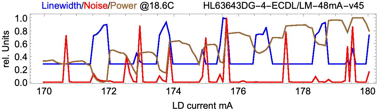
It also increased the power to about 120mW at 180mA (see power plot further above for "v45").
Wrapup: The laser is good but very cumbersome to set up/adjust. In the end, with its intermittend tendency for multimode operation, it wasn't better than other ECDL's I was playing with; which is a pity, given the sophisticated engineering. It should be useful for holography, ideally when used with concurrent monitoring of the spectrum. Perhaps it can be improved by even more tinkering and more precise adjustment, or using other diodes. I may also try to fringe lock/stabilize it, for having a good use of the piezo element.
Return to home page
Vers 1.2 6/2022