(being updated/improved 4-2022)
Return to home page
3) Design notes
4) Operation and stability considerations
Other related pages:
Detailed individual diode tests
Converting a 780nm to a 658nm 100mW+ single mode extended cavity laser
An ECDL, which is stabilized by an extra grating as feedback, holds the promise of producing just a single longitudinal mode, and a very narrow line width of a few hundred khz or so (which is not important for amateur holography). Another potential advantage is that such a laser is supposed to be less sensitive from inadvertent external light feedback; apparently, plain laser diodes can be destabilized by back reflected light even if it is weaker than 10^(-6), ie, less then a tenth of a microwatt!s.
Much can be said about this kind of lasers and I may do so later. A brief, classic read is the old Caltech Laserprimer, which concisely explains the important features in a simple down-to-earth fashion. Useful are eg. also these articles: No1, No2, and esp. No3. Note that for applications in amateur holography, the technical requirements are much less stringent as for most professional applications of ECDL (spectroscopy, laser atom traps etc), as we neither need tunability nor linewidths in the sub-Mhz region nor a great spectral purity nor extreme long-term stability. If we aim for a coherence length of a meter or so, which should be sufficient for all practical purposes, then line widths and drifts of tens of megahertz are perfectly fine. So we don't really need special custom-made, antireflection coated laser diodes and other special parts; with some luck a home-brew system with consumer electronics and surplus parts but nevertheless sufficient spectral properties can be build.
Whether this leads to a laser that can practically be used in day-to day holography, without the need of frequent retunings, is a different question. As will become evident below, single mode operation is not at all automatic, and depends on careful design (and lucky circumstances as far as the diode is concerned). Single mode zones may be quite narrow in the diode current/temperature plane, and changing the diode current by a fraction of a mA, or changing the temperature by one hundredth of a degree, can induce a jump to a different single mode. The design challenge is to safely remain in a stable zone and not drift though a mode jump or even into a chaotic zone over time, for long enough time such as to reliably shoot holograms. This requires very stable diode and TEC drivers and strict thermal shielding. We find that by careful design it is possible to stay in single mode operation without jumps for an hour or more -- at least under lab conditions!
To give some idea how differently an ECDL behaves in comparison to a free running diode, see the following movie.
This shows how the spectrum of a red laser diode (Ushio HL63643DG) changes when the operating current is changed. This is from a CCD spectrum analyzer with a resolution of 85hz (or 0.12nm) per div (in the first part, and half of that in the second). Note that the spectrum of the free running diode is mostly multimode and shifts with the current. The sound reflects noise in the power spectrum and it is strongest when modes are chaotic. The spectrum of the ECDL configuration is mostly single mode and confined to a small region. Mode jumps are sudden associated with a popping noise.
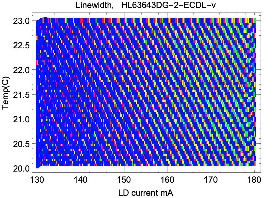
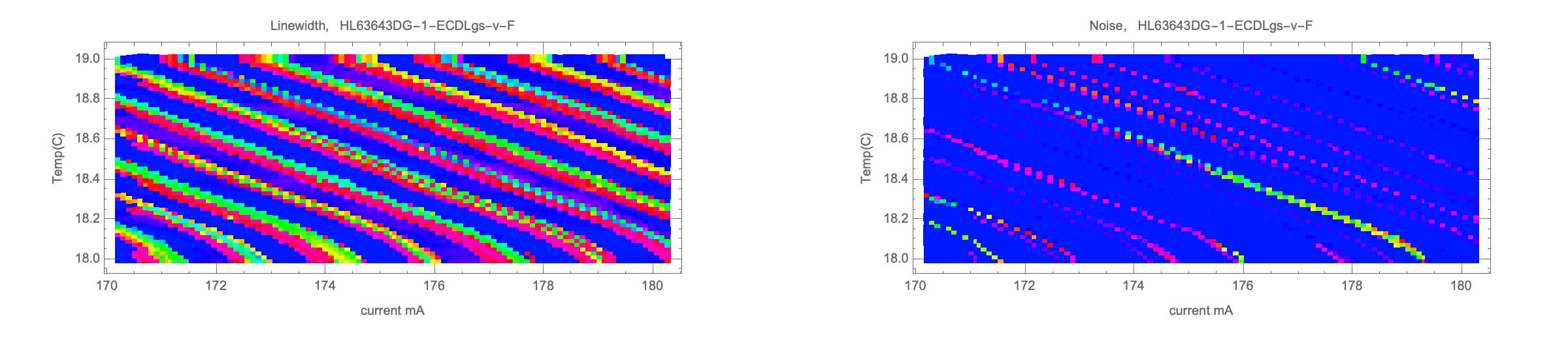
Here another comparison between an ECDL and a free running laser diode, from a different viewpoint. On the left we see a scan of the line width over the current and temperature, for a free-running diode. Blue signifies single mode regions, while other colors denote multiple modes. On the right we see what happens if the very same diode is put into an ECDL setup:
So we see that the free running diode has only a few regions with single mode operation (if at all), and they are pretty fuzzy. On the other hand, the spectrum of the ECDL is dominated by sharply delineated resonator modes, and single mode behavior is located in narrow periodic strips (ca 1mA wide) separated by mode jumps or even zones with multimode operation - exactly in line with the movies shown above. Clearly, at low powers SLM mode operation dominates, while at higher powers there is more and more competition with multimode bands. By very careful adjustment one can minimize those regions. At any rate, one has to choose a compromise between power and robustness of single mode operation. That the bands of single mode operation become smaller at higher powers is also evident by plotting just one slice at fixed temperature:
Note that these plots reflect favorable situations and in general the behavior may by far be not as nice. We present many more of such plots for a variety of diode and setups here.
All-in-all, here is the summary of what I found so far. As compared to a free-running diode laser, the ECDL configuration can yield single mode operation up to high powers (order of 100mW) and does not require cooling to low temperatures (which alleviates problems with condensation). On the other hand, the single mode zones are typically narrow, like 1mA. Stringent temperature and current stabilization, and avoiding backcouplings into the laser, is thus critical to avoid mode hops. The main problem is to either prevent, or at least reliably detect, mode jumps and/or multimode operation, into which can an ECDL can drift over time. This is not so easy as there are many parameters go into this and many of them are not easily controllable, especially without proper spectrum analyzing equipment.
2) Some more details about mode jumps
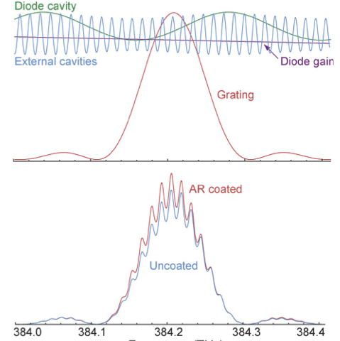
Here a few more in-depth remarks for the scientifically interested reader, as the story behind the mode spectrum is more complicated than presented so far. That is, for ECDL's based on consumer electronics diodes rather than customized ones with ant-reflection coated output facet of the laser chip, there are basically two coupled cavities: first, the internal cavity of the diode, and then the external resonator formed by the grating and the laser diode. On top of that, there is also the wavelength selectivity of the grating and the gain profile of the lasing medium.
The laser emission takes place for the mode with the largest gain when all wavelength selective ingredients are combined (we assume single mode operation for the time being). For more details in simple terms I refer to the Caltech Laserprimer, and to this paper and this paper at a higher level (most research papers focus on improving mode-hop free tunability of ECDLs, which is no issue for us). From the last one I took the following picture which shows the various contributions at the top and their combined effect at the bottom:
When the adjustment of the grating, temperature or laser current is minimally changed, then a jump to another mode occurs if that turns out to have more gain. How large could such a jump be? In principle, this jump is governed by the two characteristic scales of the system, namely by either the "internal" or the "external" mode spacing. The "internal" mode spacing of the laser diode is about 50-100Ghz while the "external" mode spacing is less, like 5Ghz. Therefore the internal one is much more severe as far as the effective coherence length is concerned, as it corresponds to a mm or so.
Thus one expects that if eg. the diode current is slowly changed, there will be a few small jumps of about 5Ghz between adjacent external modes, and when enough tension has been accumulated, then a major jump of about 100Ghz can occur. The latter would certainly ruin any hologram. So it is clear that one needs to avoid such large jumps. The important question therefore is: is that enough for standard holography purposes, or does one need to care about possible smaller mode hops on top of that? These are much harder to control due to their smaller spacing.
I had investigated this in great detail over the years, for a variety of (mostly red) ECDL setups, and found in many cases (imperatively with optimal setup and adjustment) that mode jumps are typically large, corresponding to the scale of the internal modes. Probably this is because the diode facet is not AR-coated like for commercial lasers, so the internal cavity is more dominant. I was doing this by concurrently running my grating based CCD spectrometer (resolution 4.3Ghz/pixel) and the Scanning Fabry-Perot Interferometer (about 10Mhz) running side-by-side. This is because the CCD spectrometer fully resolves only the internal but just borderline the external modes, while on the other hand its readings are easier to interpret than those of the SFPI (the SFPI cannot distinguish small and large jumps, as all peaks map back into the same free spectral range of about 1.75Ghz).
In the movie below we demonstrate this behavior. The upper scope shows the output of the SPFI and the horizontal scale is approx. 175Mhz per div. The lower shows the output of the CCD spectrometer for which the horizontal scale is about 20Ghz/div. For the movie I changed slowly the diode current by a few hundred uA and back, and you see a continuous drift in the SFPI until a mode hop occurs. At this point the peak jumps visibly also in the CCD spectrometer, namely by about 32Ghz.
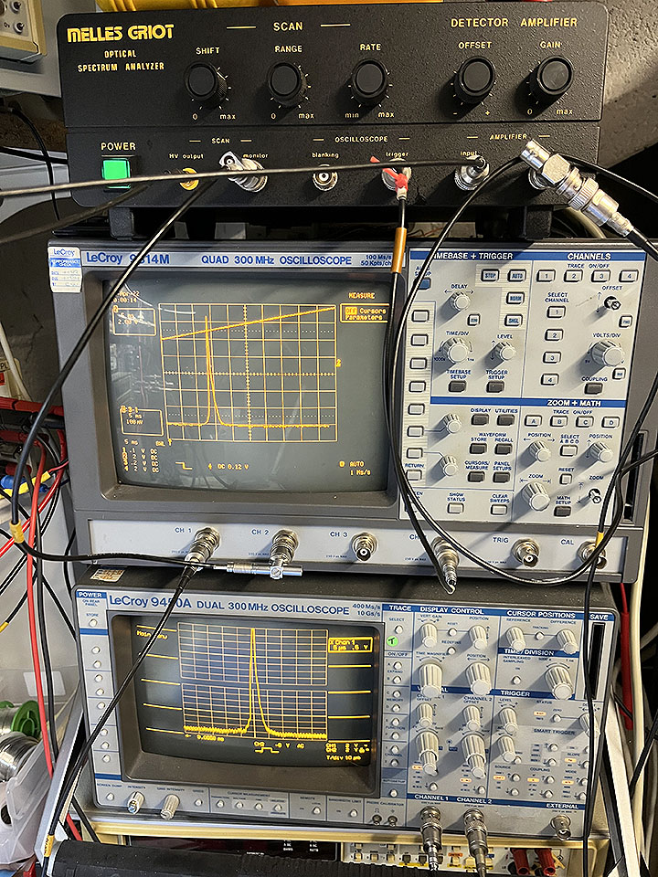
We see that in this instance, mode jumps that occur are the "big" ones governed by the internal cavity, and no "small" ones governed by the external cavity (whose spacing of about 3Ghz would be well visible with the SFPI).
However, this works in this clean way only in optimal circumstances, depending on the diode and its operating point, collimator and grating. For example, when the back-coupling is too strong, there tend to be weaker side modes that reduce the contrast of a hologram. Below there is a movie showing the spectrum of an ECDL based on the HL63133DG diode, with very strong coupling. As you see, changing the current by a mA or so can induce or eliminate such weak side modes.
Another purpose of this movie was to compare three different kinds of equipment, namely
1) a scanning Fabry-Perot interferometer (SFPI)
2) Interference pattern of the beam reflected off a glass slide a few meters away
3) grating-based spectrum analyzer (CCD)
Clearly the SFPI has the best resolution but is by far most cumbersome to operate. The CCD is best for automated scans. The glass slide is easiest to use, but it requires a very close look to judge the change of the contrast of the fringes. This is more evident in the second part with a close-up.
The issue is how to find a simple and reliable way for the holographer to deal with this, ideally automated with a feedback stabilizing system. This goes under the name of fringe locking, and part of my future projects to look into. One moderately simple approach would be to shine the fringe pattern onto a CCD linear sensor and maximize the AC signal. Stay tuned!
1) Temperature and current stabilization. It goes without saying that this is very crucial as one needs to keep the temperature of the laser diode and cavity stable up to a fraction of a degree. For a laser that would be useful in practice, one needs to add an enclosure to shield it from the slightest air currents and variations of the ambient temperature. Even more critical is the diode current, which needs to be very well stabilized too and have low noise. On the other hand, he wavelength shift per current change of an ECDL is less than for a free running diode, my investigations showed it to be typically less than 1Mhz/uA. This means that the driver board should be airtight enclosed as well. Typical windows of single mode operation are like 1mA wide, at the boundary of which mode hops occur.
In a nutshell, the current needs to be stable to better than say, 0.1mA, and the temperature better than 0.01C, over extended periods of time.
Two setups are possible: since it is far more important to stabilize the diode, one may just put the diode mount atop a peltier element. While this may seem odd at first, the ECDL described here works pretty well despite the extended cavity is not temperature controlled. The other possibility is to put both diode mount and grating on a common temperature controlled plate. This is what I mostly do, a minor problem is that the stabilization takes a longer time.
As for the LD driver, in the past I used my own driver boards described here and more recent versions described here, and digital variations of it.
As for the TEC controller, I used the controllers on the same boards as mentioned above. Most are cooling-only, which may not always be convenient. The fanciest model is fully digital and described here.
2) Feedback from external resonator is the decisive ingredient. The point is that the backcoupling (resp. feedback) depends strongly not only on the grating and its adjustment, but also on the collimation of the laser (besides the resonator length and the polarization). Typically there is a range of feedback for a given diode for some given temperature/current, for which the laser runs stable single mode (if at all). Typically this is between a few and 15-20%. This does not show so much in the output power, but rather in the mode stability. Many interdependent factors go into this, and we will go through them one-by-one.
a) Setup. The simplest way is to use a "Littrow"-configuration as shown below, where the first order reflection goes straight back into the laser, and the zeroth order (naive reflection) yields the output.
b) Gratings: One definitely needs a 1800 grooves/mm or more grating and not less, because otherwise more than one diffraction order appears, and this would reduce power. So far I mostly used such gratings blazed for UV. See the diode test page for details. For red lasers, gold plated gratings are preferred for long-term stability, despite being quite expensive.
For a given number of lines per millimeter, the diffraction efficiency depends on the wavelength, "blaze" wavelength, and also on the polarization, as is exemplified below:
(Source: Optometrics). Shown here are typical diffraction efficiencies for two kinds of holographic gratings, where the red lines refer to the polarization ("p-type") being parallel to the grooves of the grating, and the blue ones to the polarization being parallel to the plane formed by incident and reflecting beams ("s-type") . For the Littrow configuration as shown above, "p-type" thus refers to vertical and "s-type" to horizontal polarization of the laser.
c) Collimator. Its adjustment is much more critical than one might expect at first. Sometimes a minimal turn of 1mm in the 9x0.5mm fine thread of the lens holder can make a huge difference. A good way to think about it is to imagine the focus of the backreflected beam on the laser diode facet, which is just a few microns wide. Obviously such a minimal focus size is extremely sensitive to adjustment. It can be translated into the distance to the location of smallest waist size along the (almost) collimated beam, and it makes a big difference if this spot is eg. 1m or 10m away. The further away the spot is, the smaller the focus and the higher the backcoupling efficiency is, but the more delicate is the adjustment and stability. This has been explained eg. here, from which the following plot (in simplified form) is taken. It shows the backcoupling efficiency in terms of the distance to the minimum diameter spot (for a typical 4x2um diode facet):
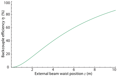
So we see that minor adjustment of the collimator can have a larger effect than the efficiency of the grating or its polarization! Adjusting it optimally may prove difficult after the unit is fully assembled. In principle this needs to be done only once, but then the collimator needs to be very well secured; not the slightest wobble is allowed. I usually start the collimation by requiring that the spot of minimal size is about 2-3m away and go from there. I also found that very precise axis alignment is important, as well as using a high-quality glass lens with good AR coating and beam profile. This means that the FL of the lens should be as short as possible and it's NA (numerical aperture) as large as possible. Best are aspheric, single lens collimators. In the past (~10 years ago), a good lens in this respect was the Lens-27 from Roithner, but among the best I found were the collimators of Marco Lauschmann. The Thorlabs Geltech aspheric lenses are superb but quite expensive. Currently I am testing the G-2 type aspheric, AR-coated glass lens that is relatively cheap on Aliexpress, and it looks pretty good too. At any rate, stay away from plastic collimators!
d) Resonator length. A priori, the distance between the diode and the grating should be as small as possible; then the external resonator mode spacing is as large as possible and this helps to prevent mode hops. However I found situations that when increasing or decreasing the resonator length by a few mm, the laser runs very unstable or not single mode at all (all other parameters held fixed).
Feedback is reduced when making the resonator long (say, >5cm), so this can be used for gratings with a large feedback (say, >20%). The wavelength selectivity is then increased as well, on the other hand the resonator modes are more densely spaced so there is an increased tendency for mode jumps. For gratings with low feedback, say 5-10%, a shorter cavity should compensate for this, but while the mode spacing becomes larger so that mode jumps are less likely, the selectivity decreases and this counteracts the stability again.
e) Orientation of polarization. Whether horizontal or vertical polarization works better, depends on the grating and the diode in question. It is important not to provide too much feedback to the laser, and it seems one should keep it at roughly 5-20%. From the figures above one infers that for red diodes an UV blazed grating is generically better for horizontal polarization and a grating optimized for visible wavelengths may be better for vertical polarization (recall that for holography, horizontal polarization is often preferred). However it seems that the gratings and the diodes vary very much and probably the only practical way to find out what works best is to try out. Note that due to the larger feedback for horizontal polarization, the maximal diode current before damaging it can be quite a bit lower... as I had to learn the hard way!
f) Adjustment of grating. The vertical adjustment of the grating is sharp and behaves like any other laser resonator in this respect, and ideally one would have micrometer screws for tilting the grating. It is just borderline doable with an Allen key. The horizontal adjustment of the grating is by far not as sharp and one has a range of perhaps 1/4 turn of the set screw on the mount, within which the lasing wavelength is just "dragged along" for a few nm. Outside of this window the internal cavity of the diode dominates and the grating becomes irrelevant. This applies to higher power operation where there is more gain. At lower powers, the adjustment range becomes smaller and smaller, until it becomes a sharp point at lasing threshold. Thus the obvious starting point is to find this spot, which can be a bit tricky to do at first, without experience.
Approximately measuring the angle of the grating and height of the beam beforehand helps to get into the right ball park to begin with. A guide to the approximate location is to watch for the reflection of the laser diode facet, which becomes visible as a transient weak dot when one is not too far away from the sweet spot. It helps to first not completely fasten the holder of the grating, and by wobbling it around at high power one can easily find this reflection near the main output. Then one can home-in to this region and fasten the grating holder and then turn the power down for finding the sweet spot with the set screws. The sweet spot is best visible when running the diode just below the lasing threshold, and when you cross it there is a flash where the power multiplies. Depending on the situation, this flash can be quite strong (red diodes) or barely noticeable (blue diodes). Final adjustment is done by just keeping on iteratively reducing the laser current and adjusting the grating in several runs, in order to minimize the threshold current. A measure of the strength of backcoupling is how much the threshold current is reduced. This can be just a few mA to tens of mA!
Now things are not that simple, though. The above procedure maximizes the backcoupling from the grating, near the threshold operation point. At higher currents the wavelength (ie., the gain curve) shifts, and in addition it is a priori unclear as to what the optimal amount of backcoupling for a given diode is, for a given wavelength.
In my experiments, I found the following pattern: if the feedback is too weak, then the laser does not easily lock into single mode but rather tends to present a mode chaos like a free running diode. If it is too strong, then there tend to be few extra isolated modes besides the main mode. Often single mode stability can be improved by readjustiung the feedback, by either changing the collimation, say moving the beam focus from initially 2m to 1m (weaker feedback) or 5m (stronger feedback) and repeat the alignment of the grating. Another possibility is to slightly misalign the grating horizontally away from the sweet spot at threshold, by very few degrees. Ideally, for each such choice, one makes a scan over the desired current range while checking the spectrum to get a judgment of the mode stability. Desired is clean single mode operation, only interrupted by mode jumps when changing the current by about 1mA. Generally the situation becomes worse with higher power, and a kind of universal ceiling seems to be about 100mW for red diodes and about half of it for blue ones. On the other hand, at low powers to about 20mW things are much more relaxed.
So you see that an ECDL is not an easy beast to conquer, and this already in a lab setup, not even to speak about a realistic holography setup!
For representative tests of individual diodes, see here.
4) Operation and stability considerations
While ECDLs can provide single longitudinal mode operation in excess of 100mW, it is nearly impossible to guarantee a "adjust once and forget" operation for extended periods of time. Due to inevitable thermal drift, diode aging, weak feedback, etc., the operating conditions change with time, producing either mode jumps (which lead to banding of a hologram), or worse, run into chaotic mode behavior where any hologram would be ruined. With a good driver and a good mechanical design, after sufficient warmup time, a laser can stay single mode for one hour or more, but earlier or later, one needs to readjust the laser. The simplest way is to make the current adjustable by a few mA in order to get back into a stable regime.
To make the point, below is some representative long term stability measurement of an ECDL running the Mitsubishi ML101J27 at 160mA/110mW:
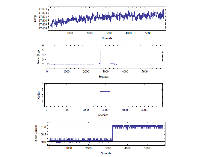
We see that after approx 2700 seconds, there was a jump to multimode operation, signified by a brief burst of noise. After some while the diode current was changed by one mA, and single mode operation resumed.
The main problem is, of course, to reliably identify and reassure SLM operation in the first place, during day-to-day holography sessions; and obviously one would prefer not having to run an OSA or scanning interferometer concurrently. One way is to monitor, and make audible, the noise in the light output, which signals instabilities. This works reasonably well for free-running diodes, but only for certain diodes and configurations in ECDLs (some investigations were summarized here). In general, there can be multimode operation in ECDLs which does not reveal itself by elevated noise.
An ordinary Michelson interferometer or scanning Fabry-Perot interferometer would most accurately reflect the relevant operating conditions, but these are clumsy, tricky to set up, and prone to destabilizing backcouplings. On the other hand, an old trick for checking diodes is to simply use a glass plate in a diverging beam, and watch the interference pattern from the reflections of front- and backsides. Such a setup is called Fizeau interferometer. The point is that the diode resonator is shorter than the thickness of the plate, so the interferometer can capture mode jumps, or even weak side modes, despite the very small difference of path lengths. Obviously such an interferometer doesn't work for other lasers with long resonator, and one might suspect that this applies to ECDLs as well, which have a resonator length of a few centimeters; in other words, one would expect that the mode spacing of the extended cavity would not be resolvable by such a short path length.
However, as explained above, the good news is that, as a general rule, mode jumps are typically much larger than jumps just between the extended cavity modes; rather the jumps occur between the native diode modes! Also, weak side modes can be detected by very carefully watching the fringes. Thus, in lack of better equipment, a least effort procedure is to send a small portion of the beam through a fl=50...200mm lens across the room, reflect it back by a microscope slide, watch the interference fringes, and restore contrast if necessary by minimally changing the diode current.
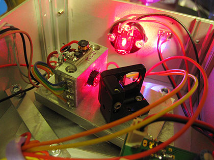
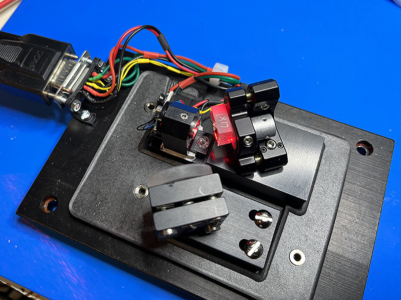
Here a pic of a most basic test setup:
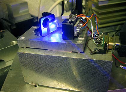
On the right there is the laser diode in a press-on mount, incl. two thermistors and collimator, while on the left you see a 1800 lines/mm holographic grating optimized for UV. It is attached to a tiny New Focus 9876-K kinematic mount, and the whole thing is mounted on a cold plate sitting on a 30x35mm peltier element for temperature stabilization.
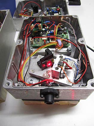
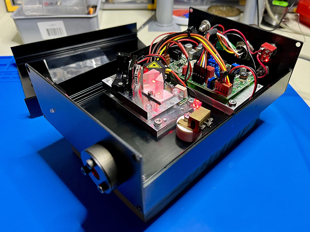
Because I liked to develop a robust design for actual use, I put together a complete unit, including my proven driver board and noise detector. This setup is very stable and easy to work with (using the expensive diode HL63133DG). Here is how it looks:
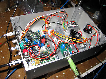
There are some plugs for remotely monitoring and controlling diode current and temperature, as well a pot for changing the current by a milliamp or so, in order for being able to move away from a mode hopping zone.
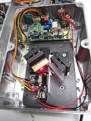
The laser unit is put separately on a head spreader block, which is mounted with a clamp such one can shift and rotate it a little, in order to have a straight exit beam. This is because re-adjusting the grating will always deflect the beam, so re-alignment of the base plate can compensate for this:
The cold plate is 8mm thick and sits on top of a 30x35mm Peltier element, which by itself sits on a 10mm base plate. The whole thing sits on a heat sink, which currently is just a massive slab of aluminum. It can be taken out as a whole, which makes changes and crude adjustments easy. Thermal coupling to the driver circuit is minimized in this way; the large common sink has enough thermal inertia in order to suppress a cross-coupling instability.
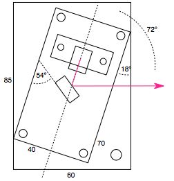
Here is a 1:1 drawing of the laser unit (dimensions are in mm, and the angles refer to a 1800l/mm grating for use near 650nm):
Here pics of some other ECDL prototypes I built (left: 100mW 642nm, right: 110mW 658nm):
The latter uses opto-mechanical parts of a commercial ECDL that originally worked at 780nm. I converted it to red light as described here.
Below a version of Jean-Claude T. using the same frame, augmented with anamorphic prisms and a G-2 collimator for improving the beam quality:
Here a close-up of the original laser which is pretty down-to earth and easy to handle:
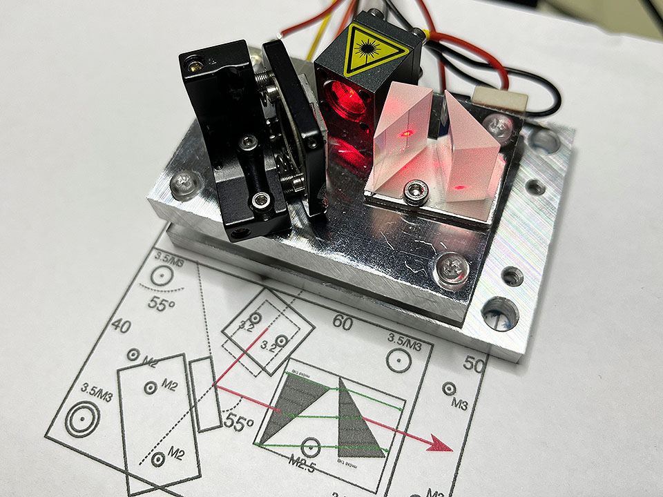
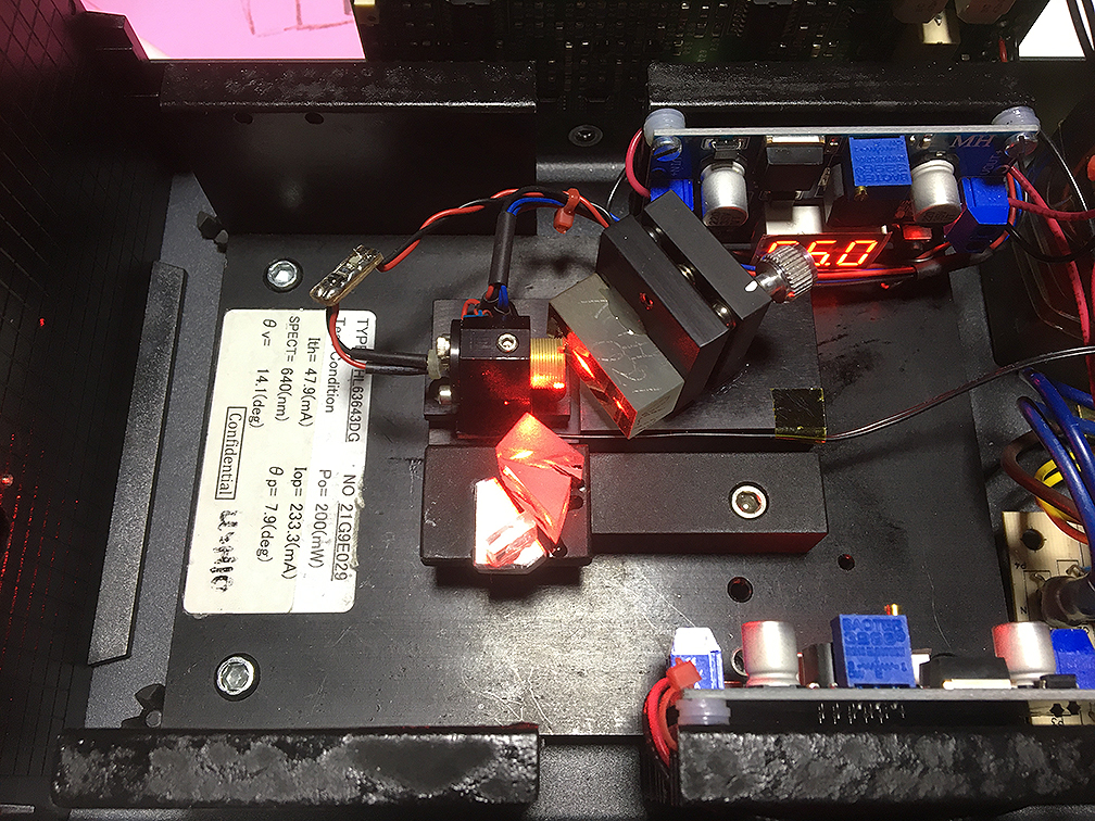
Here a new (2022) design, hosting the HL63643DG laser diode:
The aim was to have an as short cavity as possible, which means about 2cm here. The main change to achieve this was to abandon my usual more massive diode mounts and switch to a very small commercial one, namely to this one (I preferred this over the brass ones from ebay/Aliexpress, as brass has a high heat capacity and thus temperature stabilization would be very slow). It has superb quality and is perfectly suited for the task. To save space, the temperature controlled cold plate also carries a pair of anamorphic prisms for beam shaping.
This is how the complete laser looks:
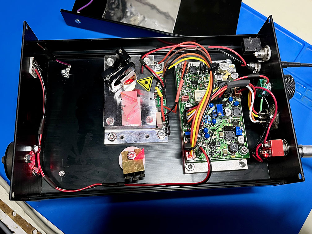
There is some extra space reserved for an eventual mode monitoring/stabilizing device still to be developed.
Here another variant of ECDL, a New Focus Vortex Series 7000 with Littman-Metcalf cavity design:

I had resurrected it from a dead diode, the full story is explained here.
Return to home page
Vers. 5.4, 6/2022