Return to home page
Local links:
A general problem of almost all lasers, and especially diode lasers, is their sensitivity to back reflections. In holography these typically arise from spatial filters and lenses that are precisely in line with the beam. The effect can be simple mode jumps but also, more likely, chaotic mode instabilities, and this would ruin any hologram. I got motivated so look for a simple solution because my diode laser heads turned out, not unexpectedly, to be sensitive as well. One would rather prefer not having to run a scanning interferometer all the time for supervision, so one should look for more simple practical alternatives, ideally something that can be integrated into the laser heads.
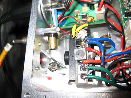
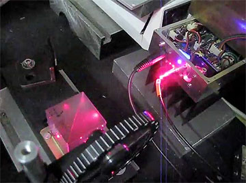
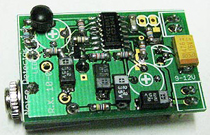
It has been well-known for a while that mode jumps can be detected by monitoring the noise in the laser output, but it was unclear whether this can be turned into something useful in practice. So I investigated and developed a simply circuit that fits onto a small PCB which could be fitted into the laser heads. In additon a small glass plate is needed to split off a tiny fraction of the beam under the Brewster angle and direct it onto a photodiode:
This is in fact quite interesting to play with. Not only mode jumps can be heard in this way, but also operating regimes with mode chaos can be easily identified by the increase of hissing noise, eg when adjusting a spatial filter. Here is a movie that exemplifies this, the current had been tuned in order to get out of a stable operating zone:
Note that there can be multimode operation also with zero noise, I suspect there is only noise when there is chaotic behavior.
Below the same is shown for an ECDL laser where there are many more mode jumps (due to the closer mode spacing). The current was monotonically decreased by a few mA. Note that there are small jumps signalled by a popping noise, and once in a while, when the mode leaves the gain profile, there is a larger jump backwards associated with chaotic noise:
Here the effect from backreflections from adjusting a spatial filter is shown:
However, due to the enormus sensitivity eben backreflections are detected that seem harmless for holography purposes. In fact the slighest amount of light, even diffuse reflections from across the room, when reflected back onto the laser diode and then onto the photo diode, can create acoustic signals. That is, the photo diode acts as a superheterodyne receiver and mixes the original signal (as "local oscillator") with the backreflected light, which has a slightly changed frequency due to the Doppler effect, if it is reflected from a moving target. The difference "beat" frequency can well be in the audible range and this is then heard as a chirping sound. This is so sensitive that almost any object the laser beam touches, acts as a microphone and the slightest disturbation creates a signal that overshadows the laser diode noise.
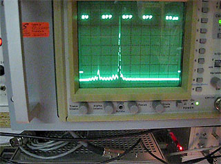
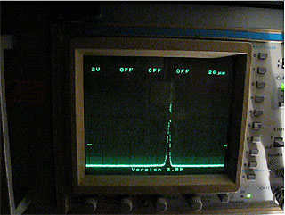
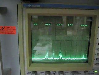
Here a movie to show this - that laser is equipped with a blue LED that flashes when there is noise in the laser output. This can be due to mode jumps, but it also flashes from relatively harmless backreflections arising when holding a finger in the beam, or knocking at the table. At the end of the movie, the outputs from the high-res scanning interferometer (yellow; lower trace=10-fold zoom at 20Mhz/div) and CCD spectrum analyzer (green) are shown. We see that knocking at the table deforms the line shape of the SFPI a bit, but only by a few Mhz, so this should be irrelevant for holography applications.
So if one wants to use this method of checking laser stability by monitoring noise, one should not be fooled by this effect and only consider a signal as relevant if _nothing_ on the table is moving.
The circuit diagram is shown here:
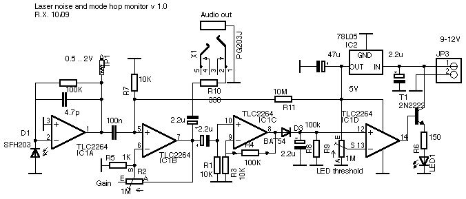
It consists of a transimpedance DC amplifier, a high gain AC amplifier, another amplifier and a comparator with adjustable threshold to drive a LED. Apart from the visual output by the LED there is also the possibility to connect PC speakers via a 3.5mm phono plug to listen to the noise.
Adjustment: The illumination of the photodiode should be such that at the test pin TP1 there is a voltage of, say, 0.2..3V. (the circuit does not work with too little illumination and near zero light the first opamp shuts off (thats because we use single supply rail-to-rail opamps). With too much light the opamp is in saturation (TP 1 at approx 4V) and all noise disappears.
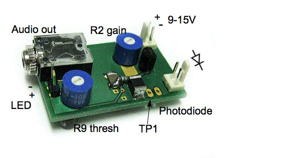
Pot R2 (gain) should be tuned to give loudest white noise and Pot R9 adjusts the noise threshold for which the LED turns on; just make it as sensitive as possible (with some safety margin so that the light does not come on when just holding the hand in the beam).
The connection to the photodiode is very sensitive and should be done by a shielded cable (unless inside a closed metal case); otherwise there will by hum from mains AC interference. Also there should not be any light on the photodiode other than from the laser.
More recently I created a space-saving version of a beam pickup at the output window by machining along the Brewster angle:
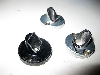
Its insertion loss is less than one percent, if adjusted carefully.
Return to home page
Vers . 1.0-04/10