By now (2022) severely outdated as far as commercial products are concerned!
Return to home page
Starting this work was motivated by Colin Kaminski. The idea was to develop reliable but affordable driver circuits and laser heads for amateur holographers, which are easy to build and reproduce. Colin's design uses commercial circuits that are simple to use but are somewhat expensive, so the idea was to develop circuits with similar performance using surplus parts that would be more affordable to the hobbyist. Some units or parts or kits are sporadically up for sale.
Overview:
1. Main problem: mode stability and thermal control; how to determine single mode operation
2. Stable, low noise laser diode drivers
3. TEC controllers, designing the PID feedback loop
4. Collimators and diode mounts
Other info:
Design studies:
Off-site links:
Colin Kaminski's holography forum and wiki, the best place for discussions on all aspects of amateur holography
Frank deFreitas classic web site on laser pointer holography
1.Main problem: mode stability and thermal control
In order to appreciate the problems of using simple laser diodes from holography, one first of all needs to know some basic facts about longitudinal modes, coherence length, mode hops, etc. For this, see for example the brief review I was writing for Colin Kaminski's HoloWiki. For useful background info on operating diode lasers, see the ILX application notes.
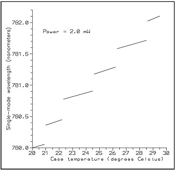
The first problem of a diode laser is the strong temperature dependence of the wavelength. It is typically as in the following picture, taken from this very useful ILX application note:
We see a quite discontinuous behavior: in between the mode jumps, we have like 0.05nm per degree C wavelength shift. This corresponds to a frequency shift of some 35Ghz, and this translates into a coherence length of about one centimeter. Thus going backwards, requiring a coherence length of one meter, say, the temperature drift should be less than one hundred-th of a degree C (during the time of the holographic exposure).
This assumes that we operate the diode far away from a mode jump. If a mode jump happens, then the wavelength shifts suddenly by like half of a nanometer, which effectively cuts down the coherence length down to a few millimeters and ruins the hologram.
The second problem is related but in a way much worse. Above we have assumed that the laser diode runs on a single longitudinal mode, the wavelength of which is displayed in the figure. But in general this does not need to be the case, and due to the large gain profile the diode may lase with half a dozen modes simultaneously, at high power it may be even chaotic. This cuts down the effective coherence length to a fraction of a millimeter, making holographic shots impossible. In the better case of just a few modes, you will get the familiar banded, "slice bread" appearance of the hologram.
In fact low power (less than 10mW, say) pointer diodes are more likely to run in single mode than the popular high power (say, 100mW) DVD burner diodes, and my measurements show that the latter are usable only to a fraction of their rated power (I found typically 30-50mW for diodes that otherwise can do 120mW in multimode).
Note that changing the operating current changes the gain of the diode and thus potentially the number of modes that lase. Moreover it changes the temperature of the junction but the temperature control, with its sensor placed at most a few mm away from the diode, cannot fully compensate for that; therefore a very stable operating current is important as well.
So in a nutshell, in order for using a free running laser diode for holography, one needs to make sure:
Point 3), 4), 5) can be achieved relatively easily by using a suitable mechanical setup whose temperature is controlled by standard thermoelectric coolers and high quality driver circuits. However the points 1), 2) seem quite hard to satisfy without suitable measuring equipment, but it is known that hobbyists were able to use simple laser pointer diodes for holography (see in particular Frank deFreitas web site). One needs quite a lot of luck to make a random diode at random current and random temperature work. However, with a variety of different methods listed below, and patience, one can identify stable zones of stability by systematically scanning through current and temperature.
Some simple methods to determine single mode operation of a diode laser:
The fringes become pronounced or blur, depending on the number of modes in the laser light, and you see also the modes jump when changing the current, etc. Obviously you will want to tune the laser for maximal fringe contrast (you may also use a CCD chip for this and display the pattern on a computer). This works because the resonator of the diode is so small, so the mode spacing is large and can be resolved by such a small interferometer. This method does not work for lasers with longer resonators (longer than the thickness of the plate, roughly), as for those one would need a Michelson interferometer with longer arms (rather: path difference).
My own, computer controlled method is essentially a combination of both using a CCD spectrum analyzer and detecting noise, see the detailed mode analysis of various popular high power DVD laser diodes. This leads to an efficient automated way to find good operating spots for a given diode.
Here is a movie that shows a fringe pattern generated by a microscopic slide, next to the output of a CCD spectrum analyzer, and there is also sound from noise in the light:
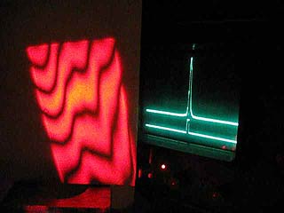
One can clearly see how a blurred fringe contrast is correlated with a distorted spectrum, and how mode jumps are audible (the fringes not straight due to the bad optical quality of the slide). Note that this shows an ECDL for which the mode jumps are more sharply pronounced as for free running laser diodes.
2.Stable, low noise laser diode drivers
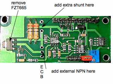
Before using my own, I used this driver as reference standard (courtesy of Colin Kaminsky). It has a good ratio between price and performance and works well for our purposes. It features low drift and less than 1uA current noise. There is not much to say about it, except perhaps that the output linear regulator runs pretty hot when there is a large voltage difference between supply and diode voltages, even at moderate currents. I preferred to reduce this voltage by an external resistor in the negative supply, in order to avoid excessive heat buildup on the board that might hamper temperature stability.
One can also use an external heat sinked NPN transistor for better stability. Almost anyone with a power rating of a few Watts will do. In fact the PCB already has connections foreseen for this, and by additionally replacing the shunt resistors one can substantially extend to power capability of the driver to like 2.5A or even more (it seems that the LD3000 model differs by nothing else than that). See the following picture.
b) W's stable, low noise diode driver
That's my own driver. It has been put together with my TEC drivers onto printed circuit boards described here and here.
c) A low-noise high-speed diode laser current controller
This is an excellent highly stable design, however with non-standard parts. The obsolete LM399 precision voltage reference could be replaced by the MAX6350, though. As for the 2ppm precision VHP-3 shunt resistor, I got a few of them - please contact me if you need one.
General remarks
To achieve a shot term stability of a few thousands degrees is in fact not so easy, and apart from the driver circuit, one has to care about the following mechanical points as well:
a) Maxim MAX1968 based TEC controller
At first I was using this left-over from my Coherent-315M DPSS controller project. It is a very efficient PWM based controller using a mosfet H-bridge, and for a description incl PCB layout and schematics, see here. Using ultra low drift (0.01uV/degree) opamps MAX4238/4239, it is one of my first good TEC controllers and typically I use it as my workhorse for trying out new designs and performing stability measurements. A disadvantage is that it uses relatively hard-to-get parts (except as samples from Maxim... ), the tiny SMD devices are a pain to solder, and quickly die by the briefest short; and trying to replace broken ones, one easily ruins the whole PCB. Therefore I don't recommend this chip to inexperienced people. Indeed, these tiny SMD devices in TSSOP cases were designed to yield high efficiency PWM controllers in a very small volume, and this is irrelevant for our purposes. Also a bidirectional mode (both cooling and heating) is not necessary for our purposes. So it makes more sense to look for simpler regulator circuits (see below).
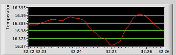
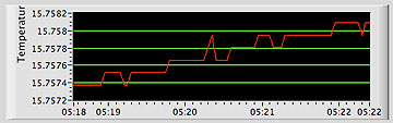
Here is a stability measurement for this driver:
On the left is plotted the temperature of the diode mount, measured by an independent extra embedded thermistor (the diode was driven with 100mA current). The x-axis is in steps of 10 seconds, so spans like 3 hours. The y-axis is the temperature, and note that it seems to be a bit noisy with fluctuations of ca 1/1000 degree (the resolution is considerably better than 1/1000 of a degree, as can be seen by the other plots below). On the right is plotted the corresponding ambient temperature which was varied in order to provoke a drift. We see the temperature drifts approx 0.02 degrees for 5 degrees change of ambient temperature.
b) My Hytek HY5600 based TEC controller
I got Hytek HY5600 TEC controller modules which provide a compact and easy solution for temperature stabilization. As per data sheet they are able to keep the temperature constant to 0.01 degrees, however it is not specified over under what conditions. Therefore I performed stability measurements myself and concluded that the HY5600 are excellent and are well suited for our purposes. A downside is that they provide only unipolar rather than bipolar drive of the peltier element (ie. they can cool only), and one has to rely on the (minimal) heating by the laser diode to counterbalance this. This means that the circuit won't be able to operate as intended for ambient temperatures smaller than the diode setpoint temperature. The latter thus needs to be in a relatively small window (say 13-15 degrees) because if the diode runs too cold there are problems with condensation of moisture. Another downside is that these circuits are not readily available, but since I got a load of them it would be a waste not to use them.
For a detailed description including measurements and an important "aha" insight, see here. This TEC controller has been put together with my LD driver onto a printed circuit board described here.
c) My new PWM TEC controller
Since I was running out of the HY5600, I was designing a new highly stable controller based on standard PWM chips. It performs at least as good as the HY5600 based one and can supply more power; the intended application is ECDL setups for the blue Nichia diode. The description is here. This TEC controller has been put together with my LD driver onto a printed circuit board described here.
d) Analog Technologies TEC-A1LD TEC controller
The TEC controller is a hybrid circuit TEC-A1LD is very stable and is used in Colin's laser head. It provides bi-directional output to the Peltier element, ie. it can both cool and heat. I received it together with a handy evaluation kit that allows to readily tune all the resistors and capacitors of the feedback loop. See Colin's laser head for more details.
e) Wavelength Electronics Temperature Controllers
There are various models perfectly suitable for holography purposes and some are not even too expensive, see eg. the models WHY5640 or WTC3243. I got the model PID1500 and hope to present some measurement data at some point. Note they sell also "new used" (eg, non ROHS compliant) devices at a reduced price!
f) Simple TEC controllers based on standard PWM chips
I designed a few very simple ones, for moderate stability, for lower and higher powers. A high precision driver is described under c).
g) TEC controllers based on power opamps
Due to the power dissipation that may backreact on the TEC, such circuits should be avoided if the controller is in the same case as the laser diode. A nice collection of circuits is here.
h) Audio IC's based TEC controllers
When combined with a precision low-drift opamp frontend and a voltage source, simple power opamps or audio ICs should be a good solution as power drivers for a peltier element. For examplle LM4860, LM4871, TEA2025 can yield 1-2 Watts of power which should be adequate for the small diode mounts. All these ICs can run in bridge mode so they can cool and heat bidirectionally; see here for an inspiration.
![]()
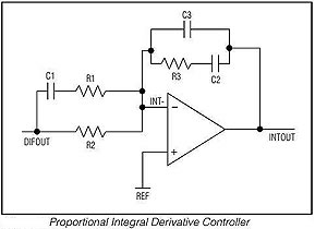
Designing the PID feedback loop
Most important for mode stability is optimizing the controller feedback loop to match the thermal load as well as possible. This depends on the mass of the diode mount, its coupling to the TEC, the coupling of the embedded thermistor, etc, and this can be quite different for different constructions. The crucial part of the feedback circuit is a "PID" (proportional integral derivative) controller shown as below. It can be used as part of any circuit, eg of a linear or PWM regulator.
In order to obtain maximum short- and long term stability, the following electronic design features are very important:
In short, the main point is that the combined TEC driver/Peltier/LD mount/thermistor system has a certain delayed response function due to thermal lag, which may be viewed as a (frequency dependent) phase shift. A phase shift of 180 degrees means positive feedback, and it gives rise to oscillation when the total gain is positive at that frequency. Thus the primary design goal of the feedback loop is to provide enough compensation of the phase shift in order to allow stable operation at highest possible gain. Other aspects like quick settling time after perturbations and small overshoot are not as relevant for the present application, but it does not harm to optimize those as well.
The method I adopted is to first measure the open-loop response of the combined TEC driver/Peltier/LD mount/thermistor system. This is done by cutting the feedback loop open, eg at the controller input, and feeding in a sine signal from a function generator (obviously at appropriate amplitude and DC offset levels as required by the particular circuit under investigation). The output from the other "open end" is fed to an oscilloscope, and its amplitude and phase is compared to the input signal. This has to be done over representative points in the relevant frequency range, which is like 0.001... 1Hz. In view of the long times at the slow end, a digital storage oscilloscope, or some other digital machinery like a data logger, comes very handy. Below a typical picture:
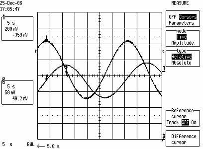
The relative amplitude and phase can then be plotted over the frequency to yield so-called Bode diagrams.
The following ones were obtained for the diode mount described below, in conjunction with the 20x20mm Peltier and the TEC-A1LD controller:
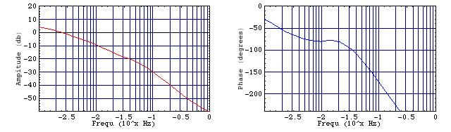
Next thing to do is to determine the location of the first and second poles, which is where the phase becomes -45deg and -135deg, resp; and the gain near the second pole. These data are then used with the rules given in the MAX1978/79 data sheet and here to determine a reasonable choice for the resistors and capacitors of the PID feedback component.
These rules give (from my experience) very reasonable but conservative values, but they may not be necessarily 100% optimal and some tweaking here and there can improve the gain by some 10db while keeping sufficient phase margin. What I was doing in practice was to use these values as starting point for an interactive optimization procedure; a while ago I made a crude LabVIEW program for this, but now since Mathematica 5.2 provides simple widgets for GUI interfacing, I made a little program within Mathematica to do this better. Here a pic of the applet window:
All what is needed is to move the sliders in order to obtain as much total gain (red, in db) as possible, while preventing the total phase shift (blue, in degrees) to reach below approx -150 degrees (whenever the gain is positive). The Mathematica 5.2 code is available here (demo versions of Mathematica do exist).
5. Collimators and diode mounts
![]()
For the collimator, I recommend model Lens-27 of Roithner which yields very high power due to a single aspheric lens with high NA (numerical aperture). Apart from the relatively high cost, a drawback is the poor beam quality for certain diodes, like the Opnext HL6385DG, due to diffraction artifacts from the edges. This maybe a nuisance for holography. Another very good choice is the G-650-1, which has slightly less power but a considerably better beam profile. I obtained it from here. Low cost variants are the coated glass collimators from Aixiz.
Here a comparison of lenses I tested:
| Collimator | rel. Power (mW) (658mn) | beam quality |
|---|---|---|
| Aixiz uncoat. plastic | 97 | medium |
| Aixiz coated glass | 100.5 | good |
| Roithner GS 8019A | 101.3 | very good |
| G-650-1 | 108 | very good |
| Roithner Lens 27 | 112 | medium |
| Thorlabs C230TME-B | 115 | very good |
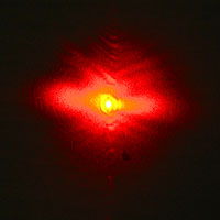
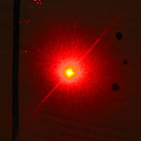
Here a comparison of beam profiles, at a distance of approx 5m. In order to cut down the brightness of the center dot, I placed a black spot with a marker pen underneath; so the ratio of intensities of the beam center and its halo is much better than it appears:
| ML101F27 (658nm) | HL6385DG (642nm) | |
|---|---|---|
| Roithner Lens 27 | 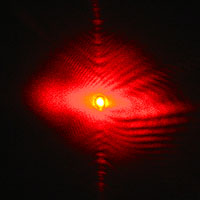 |
 |
| G-650-1 | 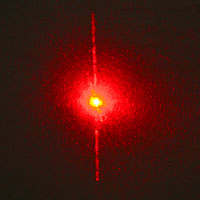 |
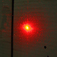 |
| Roithner GS 8019A | 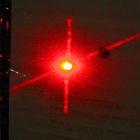 |
 |
| Aixiz coated glass | 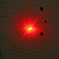 |
See here for blue 445nm laser diodes.
My mounts are modular and consist of 20x30x15mm or similar aluminum bricks with a 9x0.5mm fine thread. The diode is clamped onto the mount from the back side. All the mounts have a reverse Schottky diode and a SMD 10uF cap for ESD protection installed (or a Lasorb for the more expensive diodes) so in order to change a diode it is easiest to simply replace the whole mount with all the protection staying in place. I also put so far two thermistors in order to have one free for precise temperature measurement. They are glued by Arctic Silver two component thermal compound as close as possible to the diode. A 1703 style peltier element of 15x15mm^2 with current of approx one ampere max is just fine for these mounts.
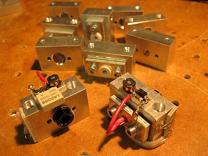
In order to avoid the painful cutting the fine thread, I also use for test setups the familiar Aixiz blank diode module casings which give a very tight press-fit for the diode (I guess one cannot remove the diode from it anymore in a non-destructive manner). The outer tube has a diameter of 12mm and this then fits in a 12mm hole of the mount, filled with Arctic Silver thermal grease and held by a screw. I believe that the non-optimal thermal coupling of the tube to the brick is compensated by the tight fit of the diode, and I found that the thermal properties of this mount do not noticeably differ from the other mount.
Clamp-on style mount with 20x20mm Peltier element:
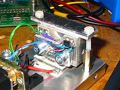
I performed a Bode analysis for this mount and the MAX1968 based TEC controller, and it comes out as follows:
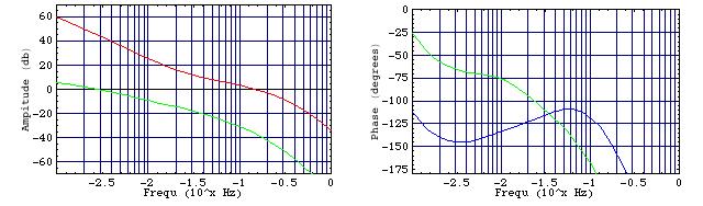
The raw uncompensated data shown in green. The red and blue curves show gain and phase after compensation with the PID feedback loop. Note the very high gain at around 1mHz. The corresponding optimized values for the resistors and capacitors, referring to the PID control loop shown below, are:
R1=1KOhms
R2=560kOhms
R3=1MOhms
C1=6.8 uF
C2=5.6 uF
C3=0.01 uF
These values assume an extra gain of 20db of the preamplifier which is part of the controller circuit.
Vers 2.0 04/2011