Return to home page
The starting point of all my investigations about diode lasers was the laser module by Colin Kaminski who sent me a complete system and asked whether I could tune and/or improve it. It uses commercial available laser diode driver and TEC controller circuits. Specifically, the constant current LD driver is the Thorlabs Model LD1255, which is of high quality in that it is very stable and has little noise (1uA rms). Moreover, the TEC controller is a hybrid circuit TEC-A1LD which too is very stable; it provides bi-directional output to the Peltier element, ie. it can both cool and heat. I received it together with a handy evaluation kit that allows to readily tune all the resistors and capacitors of the feedback loop.
So far I was using this laser with the Rohm RLD65PZB5 100mW/658nm laser diode, for which I have collected a lot of measurement data. It is a higher power DVD diode which is certainly not optimal for this purpose, but it seems generically to be good up to 30-50mW when operating in a suitable, stabilized temperature/current regime.
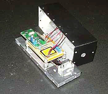
I modified Colin's original design concerning the diode mount, as it didn't have a provision for collimating optics. So I manufactured a new, larger mount with a 9x0.5mm thread that can host standard collimators, eg. the ones sold by Roithner. I recommend model GS-8019 which yields a beam of good quality. The new mount is a small aluminum brick of 20x30x15mm, and uses a clamp to press the diode against the back side. As it is easiest to design for just one standardized construction, I will consider here only this mount, which is relatively easy to make by oneself; in fact, I have also found a person who is willing to manufacture these mounts against a fee, see here.
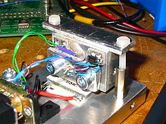
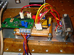
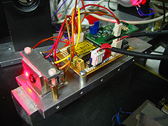
It turned out that the original Peltier element was a bit too small for the new mount (and it broke anyway), so I put in a stronger TEC whose size is 20x20mm. Since that obstructed the mounting holes, I had to cook up a holder as well, and now clamp the mount against the Peltier element. This allows easy and quick modification of all components for experiments, and also provides excellent thermal insulation. A few pictures are below.
Next thing was to optimize the feedback loop for this particular configuration; the procedure incl some measurement details is described here. In terms of the resistors and capacitors defined in the TEC-A1LD data sheet, the result is:
Rd=100kOhms
Ri=1.5MOhms
Rp=4.7MOhms
Cd=4.7 uF
Ci=0.68 uF
The control loop is stable and worked well right on the spot, below is the pic of a near perfect, critically damped response to a step decrease of setpoint temperature by 5 degrees C:
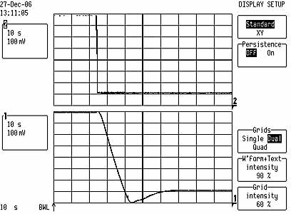
(x-scale is 10sec/div)
Below are some long term stability plots for the complete laser head, extending over several hours (after approx 1/2h warmup time). The Rohm diode was runnning at 90mA and temperatur setpoint voltage at 495mV (approx 18 degrees C), and these values hat been determined by a combined linewidth/noise scan. The output was measured at approx 32mW.
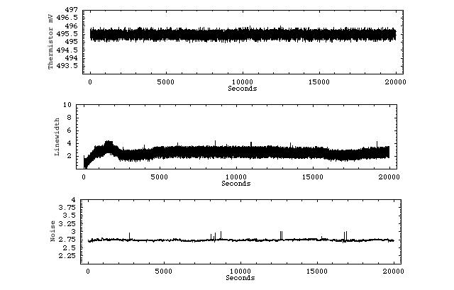
The top diagram shows temperature measured with 16 bit resolution. It stayed constant up to a few throusands of a degree.
The middle diagram shows the "effective" line width as measured with an optical spectrum analyzer as described here. A value of 3mV corresponds to single mode behavior.
The bottom diagram shows virtually no noise in the output. The little peaks are spurious, as a mode jump typically induces a much larger burst. This means there was uninterrupted single mode behavior over several hours!
Return to home page
Vers . 0.4-02/09