Reference design based on the Newport 700 TEC stabilized diode mount
Return to home page
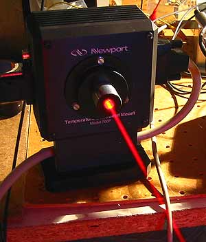
The mount:
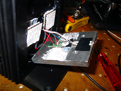
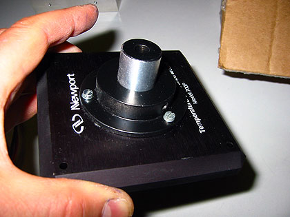
I was fortunate to get one of those mounts, however the model "P" for pigtailed diodes and thus without provisions for mounting collimator optics. So I retrofitted it with a new aluminum plate to hold the diode, and used some spare metal parts to mount a collimator on the outer shell. It is quite awkward to adjust but then rather stable. This has the advantage that the collimator does not touch the diode mount and so cannot feed any temperature gradient to it; I think this is very important. The cold plate on which the diode sits does not touch anything else than the two Peltier elements and are held in place by insulating plastic screws. I still need to check long-term temperature stability; for this purpose, an extra independen thermistor was added.
At any rate, the construction is simple enough so one can just go and build a similar mount rather than spending $$ on a commercial one. Here are some pics, perhaps they inspire someone else.
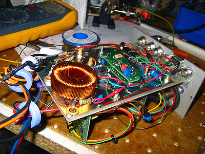
Above: The whole thing is mounted on a solid lead brick of 5(?)kg - that helps keeping it in place.
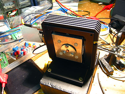
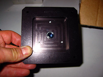
Below: This is the aluminum cold plate and diode mount. The dimensions of the plate are practically the same as for the original Newport one, so the thermal properties should be similar as well. For the measured TEC controller open loop response and an optimized design of the PID feedback loop see below.
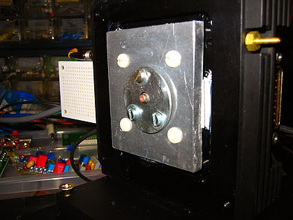
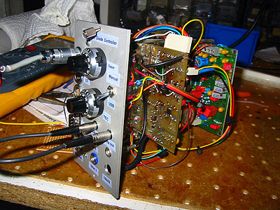
Below: a home made collimator holder, thermally isolated from the cold plate.
Now on to the dynamical thermal properties. So far I am using an ultra-stable TEC controller that is a left-over spare from my Coherent 315M DPPS power supply project. It features virtually zero-drift (10nV/C) opamps and is explained in more detail here. It is supposed to keep the temperature constant up to a few thousands of a degree, over an extended period of time. However the time constants in the PID loop had to be modified for optimal temperature response and for avoiding oscillations. Similar as explained on that page (and more recently here), I measured the open loop response of the thermistor-controller-TEC system and obtained the following Bode plots (amplitude and phase responses to the left and right, resp):
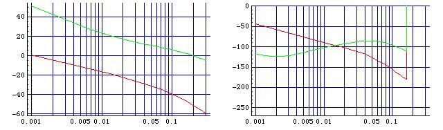
The x-axes denote the frequency in Hz, and to the left the y-axis denotes the gain in db and to the right it denotes the phase shift in (angular) degrees. The red curves described the measured response, while the green lines show the computed effect of the optimized feedback loop. For stability it is important that for positive gain, the phase shift stays away from -180degrees; indeed the green line on the right fulfils this very well. The key piece of the PID feedback circuit is as follows:
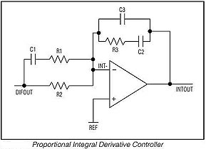
The green lines in the plots above correspond to the following values:
R1=0
R2=470KOhms
R3=4MOhms
C1=6.8 uF
C2=10 uF
C3=0.01 uF
One can use this as a piece of another TEC controller circuit, as long that doesn't induce a major phase shift. The overall gain should be adjustable, of course. I expect the original Newport diode heat sink to have a very similar thermal response, so that the values of the resistors and capacitors shown here should work well also for the original, un-modified Newport mount. For further notes, see here and here.
The laser diode driver:
So far, as reference standard I am using the Thorlabs Model LD1255 constant current laser diode driver (courtesy of Colin Kaminski). For further info, see here. I was putting in a lot of extra filtering in order to use a standard switchmode power supply, and still have a clean output as much as possible:
Below some measurement data from a run over more than four hours (with two hours or so settling time beforehand).
The chosen operating point was "spot K" in this diagram, with 99mA laser current and 54mW output power.
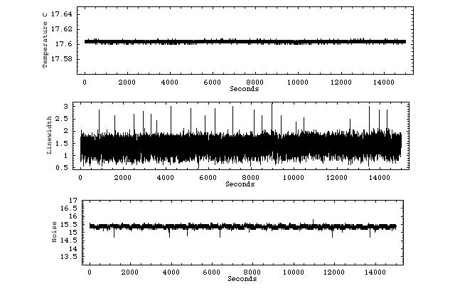
The top diagram shows the temperature measured with an independent second thermistor, coupled to a 1ppm/C precision voltage source MAX6341 and a MAX1169 16bit ADC. The temperature stays constant to approx 0.005 degrees, and no drift is visible!
The middle diagram shows the "effective" line width as measured with an optical spectrum analyzer as described here. A value of 1.5mV corresponds to single mode behavior. I am not sure what to make out of those brief peaks - dual mode behavior should correspond to 7mV or so, thus it seems that those are spurious signals.
The bottom diagram shows the noise in the light output, and a mode hop should be signalled by a brief but drastic increase of noise. No such peaks are seen, so it seems there was no single mode jump over the full four hours!
Return to home page
Vers . 0.6-02/09