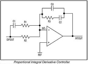
The crucial part of the feedback circuit is a "PID" (proportional
integral derivative) controller shown as below. It can be used also as part
of your own circuit, eg of a linear regulator, and the same RC values can
be used if there is no major other phase shifting element in the signal path.
Best is to have a pot for adjusting the overall gain by hand, to find the
maximum stable gain by trial and error.
In practice there is little hope to obtain the desired long term accuracy of
0.01 degrees or better, together with good control loop behavior (in particular,
no oscillation), if the design of the feedback loop is not optimal. Some illuminating
literature and practical rules about the design of PID feedback loops can eg. be found from the following
notes: MAX1978/79,Analog
Devices AN-695 and here.
In order to obtain maximum short- and long term stability, the following design
features are very important:
Use high quality (low leakage, unpolarized) film capacitors
(eg Wima MKS2), and not tantal or electrolytic caps, for C1, C2 above.
Use no ceramic but also a film capacitor for the small cap C3; ceramic
caps show a small pieco-electric effect which can affect the stability.
Use only low-noise metal film resitors and not carbon resistors.
Use low noise and extremely low offset drift operational
amplifiers for the feedback loop. With standard op amps like the 741 one
cannot hope to obtain any decent stability over temperatur changes. The
input and output regions of the feedback circuit should be decoupled (ie,
far apart) and very well insulated from each other - recall that we talk
here about voltage drifts in the uV range. This also means to avoid IC's
with contain both input and output op amps in the same package.
Decouple the input/output sections of the PID circuit on the printed circuit
board, by having them far apart and/or by having a guard ring connected to ground
between them; this reduces leakage (eg due to surface moisture) that would
lead to drift.
For orientation, here some data of my system running at equilibrium at I(LD)=1.93A,
P=95mW, ambient=23C (voltages measured at controller PCB output terminals,
not at the laser head):
Temp
I(TEC)
U(TEC)
Chip
LD
16.1C
0.7A
5.23V
LTC1923
KTP
23.7C
0.02A
small
MAX1968
RES
22.5C
0.3A
3.90V
LTC1923
Under these conditions, it would be possible to drive the resonator TEC also
with a MAX1968
which can deliver close to 5V; obviously, for the LD this does not work.
All TEC circuits must have adjustable current limits, if possible independent
for cooling and heating. It is safest to allow only for moderate heating for
KTP and RES, and no heating for the LD TEC's. I chose the following limit
values:
KTP: 125mA cooling, 80mA heating
LD: 1.5A cooling, 100mA heating
RES: 1A cooling, 300mA heating
Note that a with increased heating limit (1A) of the RES TEC, I had repeatedly
encountered thermal runaway (heat was so quickly introduced that the circuit
didn't catch up with removing it, and the temperature rose to more than
45C before I could shut it down). That's another good reason for a safeguarding
shutdown circuit, which is provided by the LTC1923 but not by the MAX1968
circuit.
I had a couple of surprises in terms of burnt-out chips, and this was due
the low (0.5A) current limit had I put on the lab power supply used to test-drive
the circuits. The moment the current limit was reached, oscillations occured
which eventually killed a few MAX1968's. Initially I thought there was an
inherent design flaw, but all problems went away after I courageously tuned
up the lab ps's current limit. So, being careful in the wrong way may do more
harm than good...
For the KTP and LD TEC controllers, I use the values for the capacitors and
resistors more or less as in the MAX1968 data sheet. This works well with short settling times, no serious overshoots
and no oscillations. On the other hand, for the resonator TEC there was low-frequency oscillation with period of ca 20s, because apparently
the thermal time constants of the resonator assembly differ quite a bit from
those of standard LD modules, and so I had to redesign the feedback loop.
This is described further below.
Some plots showing the loop responses for sudden changes of temperature control
voltage are presented in the measurements section.
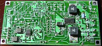
2) MAX1968 based controller for the KTP TEC (borderline
useable also for the resonator TEC)
It works very well for the KTP TEC. As said above, the MAX1968
is borderline for using it for the resonator TEC. It is possible to use it
if the ambient temperature is moderate; otherwise, the limited output voltage
does not allow to get the necessary amps through the two Peltier elements
in series. One may try to add a floating constant boost voltage source (of
2-3V, say) in series to the output (of course, one may try this also for the
LD TEC). However I didn't do this so I cannot say whether it works satisfyingly.
The MAX1968
is tricky to cool; just taken as-is, it can deliver only a few 100mA without
overheating (which is enough for the KTP TEC only, for this I have set Imax
to 125mA). It has a metal base plate on the bottom, which may be carefully
soldered through a hole to the back side of the board. After doing so, the
IC's can easily deliver 1.5A and more without getting hot. At any rate, they
are easy to ruin, the briefest short of an TEC output to ground or +5V damages
the chip instantaneously (while a short between the outputs is curent limited).
As for the op amps, the board is designed to host either one MAX4475/4477
pair (as per the MAX1968
data sheet), or alternatively three ultra-low offset drift (10nV/degree) MAX4238/4239
for improved stability. The latter are preferable for use with the KTP, and
the former are fine for use with the resonator TEC. With this setup, one may
build two such circuits without needing more than two of each type of integrated
circuit (which is, incidentally, the limit Maxim has for sending free samples...)
The schematics is here. It is
drawn only for the MAX432x op amps, the alternative circuit for the MAX447x
(included on the same board) is the same.
The values of the PID controller parts R1-R4 and C1-C3 as shown, are for
use as controller for the KTP TEC; for the RES TEC take the values as described
below in 4), and R4=10K. For the LD take R4=10K and C2=4.7..10u (as in the
data sheet), but as said above, the output voltage is not high enough in order
to allow high laser power.
The three 100K pots allow to set max TEC voltages and currents, see the
table above.
The single 100K pot allows to zero the offset between thermistor signal
(TH) and adjustment voltage (ADJ); this is not important but makes digital
operation easier.
The J-2 pinhead can be jumpered for different configurations; 3-4 allows
to use a single 5V source, 5-6 can be jumpered for using the internal reference
of the MAX1968 (jumpered as shown, it uses the system wide 4096mV reference);
9-10 allows to open the signal path for allowing measurements (Bode plot)
and trouble shooting.
The number and location of bypass caps between the schematics and the board
do not completely match, I used more or less what is shown on the board (not
critical).
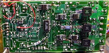
3) LTC1923
based TEC controllers for the LD and resonator
This circuit is more involved than the MAX1968 based one, but is also more
powerful -despite being quite small, it can deliver 2.5A up to 20V or more
output. It has also some fault detection features. I use it for both the 315M
laser diode TEC and the resonator TEC - the values for R1-R3 and C1-C3 of
the PID feedback loop are for the RES TEC as described below, while for the
LD they are as indicated in the schematics.
The schematics follow closely
the LTC1923
data sheet, but I have adapted the circuit to the application at hand,
and to work together with the other 315M controller components. Besides the
LTC1923 PWM regulator, it uses an ultra low-drift instrumentation amp LTC2053,
a pair of mosfet drivers LTC1693-1
for level shifting, and a two IRF7343
dual P/N pairs of power mosfets for high voltage switching.
The circuit runs smoothly but needs thoughtful adjustment of the pots on
the board. P1 is for overall gain and
it should be tuned down until stability under all conditions is guaranteed.
This is pretty easy for the RES, but for the LD it turned out, initially,
that after reaching the max current limit (set by P2, for data see the above
table), there was some tendency for sporadic oscillation - this occured ca
1/2h after start, when the heat sink started to warm up and higher cooling
power was needed. This problem was cured by reducing the gain. P3 can be used
to cancel the offset voltage between the "TH" thermistor output
voltage and the "ADJ" control voltage - this is handy for the digitial
interface, but otherwise not really necessary. P3 and P4 can by used to limit
the max TEC voltages - also not too important, they can be left out with the
wiper pin grounded. I also included an extra choke in the 12V (really: 10-20V)
supply line, otherwise there are considerable switching spikes induced on
it. With all the filtering the high frequency switching noise is a few thens
of mV on the TEC and supply lines.
The connector J-1 links to the data board and is pin compatible with J-1
on the MAX1968 based TEC controller; similar for the output block J-3 (except
12V instaed of 5V is needed). J-2 is for measurements and supervision; FAULT
can be connected to a relay (and LED) used to shutdown the whole controller
(which is absolutely necessary, otherwise you may grill your diode without
noticing until it is too late); H/C can be connected to a LED as well for
heating/cooling indication.
4) Designing the feedback loop for the resonator TEC
After numerous fruitless attempts of random tries to kill the loop oscillations,
I decided to adopt a systematic procedure, and measured the open loop amplitude
and phase response (between the control input of the IC and the thermistor output).
For this I could directly use the digital interface, as the involved time scales
are fractions of a Hz, so this posed no problem for the low-speed USB interface.
The input and output waveforms were displayed via a little LabVIEW program:
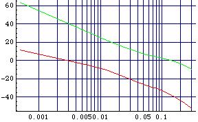
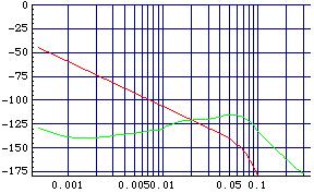
Reading off amplitude ratios and phase delays, the Bode diagrams
(amplitude (db) and phase plots of the combined controller-TEC system) come out as
follows (red lines):
Suitable values for the capacitors and resistors in the PID feedback loop
(the part of the circuit shown above) can be determined eg from the rules
given in the MAX1978 data sheet. Somewhat problematic is that the required R and C values are quite
large - film capacitors larger than a few uF are expensive, while large resistor
values require excellent isolation (no moisture). I made some compromises reflecting
the capacitors I had, and the values I chose are listed here (referring to the
PID circuit above):
The computed compensated loop response for these values is shown by the green
lines above - there is now a sufficient phase margin, ie the phase stays away
from -180 degrees for positive gain, which means that the closed feedback
loop should be stable (these computations have been done using the nice Mathematica
(demo-)package from Analog Insydes;
professionals would probably use PSpice, but I happen to be used to Mathematica).
The resonator TEC feedback loop them turned out to be indeed stable (when properly adjusting
the overall gain).
Note added: I used the same guidelines as described here (mainly based on the rules given in the MAX1978 data sheet) to design PID feedback loops also for various red diode laser modules described in more detail here.