Return to home page
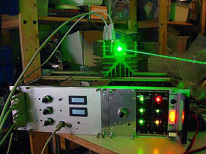
The Coherent Compass 315M-100 is a small and sweet DPSS laser head that is relatively cheap to get on the surplus market and ebay and offers approx 100mW of single mode output at 532nm. Running single longitudinal mode is crucial for holography and this sets the head apart from generic DPSS lasers, like tuned-up laser pointers or low cost DPSS heads suitable for show applications. (I had contacted a Coherent representative and he said that the head is not fully single mode but there is another line ca 1nm away, however with 1% or so of the total power. This shouldn't harm holography applications, however so far I did not yet make any hologram with it and thus do not have an image quality comparison with a single mode argon laser).
However, acquiring the laser head with original controller is much more expensive than the bare head. Thus I decided to build a controller by myself, and it was mainly the amount of crucial and detailed information in Sam's Laser FAQ (especially here) that gave me the confidence to try this. Though I must say this was much more work than I expected..... I did it for fun and as challenge and to learn something new, but if somebody just wants to have the laser head quickly up and running, and/or doesn't like electronics, he may be better off by acquiring the original controller.
Also, if one would need to buy all the components, incl the case, power supplies etc (rather than having them on stock or ripped out), then it may also not be much cheaper to build the controller rather than buy the original one. At any rate, the whole project was supposed be as least pricey as possible, and that's why I started out with integrated circuits by Maxim, TI and Linear Technology, for which samples can be ordered for free. All these IC's are tiny SMD devices, which are pretty much impossible to use without printed circuit boards, and even then they are difficult to solder; one really needs experience as well as patience for soldering leads with 0.6mm pitch.
In the following I describe this project, so that others can have some inspiration for their own projects. Of course, no warranty is implied for the correctness of the description and I do not assume any sort of responsibility or liability for damages, etc. The whole projected should only be attempted by someone with sufficient electronics experience, keeping in mind that a laser diode is ruined very easily.
For holography applications, the laser must be as stable as possible and should have as little mode jumps as possible, after warm-up. This requires ultra-stable laser diode drivers and TEC controllers, the latter ones should allow to keep the temperatures of laser diode, KTP crystal and resonator very constant, at least for the KTP to better than 0.01 degrees celsius. This requires suitable circuits involving high-precision (ultra low drift) and low-noise op amps, and a very clean and well-filtered setup avoiding any sort of ground loops etc.
A major problem is to find the best (or at least good enough) stable operating point, which is a maximation problem involving several variables (3 TEC controllers, for a given fixed laser diode current). The idea was to add a digital interface for reading and writing these data, and let a computer help doing the work and determine once for all a good stable "sweet spot". Once a good setpoint is found, the values are set by external potentiometers, so that one can run the laser without computer.
Of course the idea was to use the individual setpoints for the TEC's (provided by the trim pot settings on the laser head) as starting points for any optimization procedure. However I found that some of the setpoint settings on the head were so far off (eg, the laser diode temp was supposedly at around 7 degrees Celsius), that they were completely useless. On the other hand, this did not matter much because with the digital interface, good operating spots can be quite easily found. This is done by performing systematic temperature scans, and after a few iterations the procedure converges quite quickly. While the scans by themselves are automated (controlled by a LabVIEW program, see below), the whole iterative procedure is done by hand, as this works well enough. I abandoned initial hopes to do the whole setpoint optimization automatically (have a look at the measurements section to get an idea, why), and remain wondering how the original controller by Coherent achieves this reliably.
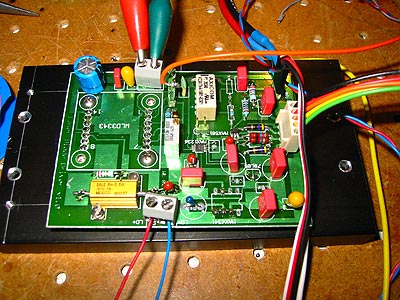
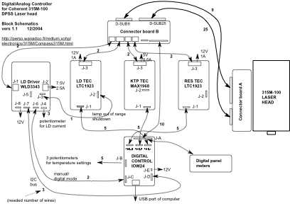
This needs not only to be very stable but also must provide sufficient safety margins to keep the laser diode alive, ie, it should have all sorts of overcurrent and surge transient protections, a soft-start behavior and so on. For these reasons I decided not to risk the valuable laser head and play safe, by using a commercial LD diode driver module WLD3343 (as suggested in Sam's Laser FAQ). These units are expensive but can also be bought refurbished (supposedly fully functional but with slightly more noise) from the manufacturer for less than $60. Digital control is provided by a MAX1236 ADC and a MAX5812 DAC chip, in combination with a MAX6341 precision voltage reference.
More details can be found here.
I decided to first give the MAX1968 chip of Maxim a try - their data sheet mentions that it would be possible to achieve the desired 0.01 degrees long terms stability. The advantage of a PWM controller as compared to a linear regulator is much better efficiency and smaller size, since heat sinks are not necessary; also, generating less heat improves on the thermal stability. The data sheet also proposes a PID circuit involving high-precision op amps, which I have put (with some modifications) on the same PCB. See here for a more detailed description.
However, due to long cabling and the fact that the LD and resonator TEC's each consist of two Peltier elements put in series, the required voltages at full throttle is beyond the max 5V the MAX1968 (and similar chips of TI, Linear and Analog Devices that run around 5V) can provide. While the MAX1968-based controllers for LD and cavity work very well for usual room temperatures and LD currents up to ca 1.8A, one needs more TEC power in a hot environment and for higher laser power (again, the problem is not the amps but the voltage that is necessary to get the amps flowing). I thus built a circuit using the LTC1923 which uses separate higher voltage mosfets. This circuit is more complicated to make, but provides substantially more power such as to cool the laser diode beyond 2A current, and at elevated ambient temperatures. Moreover, it also provides shutdown features for the case the temperatures get out of control, and this is very important for safeguarding the laser diode.
Having done some measurements, it turned out that the temperature stability requirements for the LD and the resonator are not as stringent as what I expected; so probably some simpler circuits would do for those two TEC's. For the KTP, stability to 0.01 degrees or better is definitely necessary.
For further remarks on the TEC controllers and their design, see here.
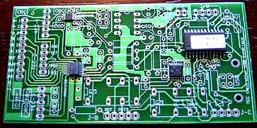
A new fresh layout, with the SMD ICs already soldered in place:
Alltogether the analog-digital USB interface board provides three16bit write and three16bit plus eleven 12bit read channels, apart from a few digital I/O channels for remote control of "digital control off-on" and the holography shutter. All digital IC's interface via a I2C bus to a IOWarrrior24 chip which allows for direct USB hookup to a computer.
More details are here.
I made two LabVIEW programs for controling the laser head:
1) A simpler "production version" for just using the laser head, which also includes a timed holography shutter control and a mechanism for locking the KTP temp for max output power. This leads to an ultra-stable output over extended periods of time:
In locked mode, continuous small adjustements of the KTP temp are visible (blue line= thermistor voltage, white line= control voltage) - the fluctuation amplitude is approximately 0.2mV which amounts to about 0.005 degrees. The output stays constant to a fraction of a mW; mode jumps are virtually absent. On the other hand, in standalone mode without computer control, there is some (not grave but noticeable) drift to the effect that one needs to re-adjust the KTP temp by a few thousands degrees once in a while; mode jumps are still almost absent.
2) Then there is a more sophisticated "development version" which allows for systematically scanning the LD, KTP and RES temperatures, in order to "once for all" determine the best operating spot. Below a pic of the latter with KTP temperature scan mode activated - this helps to identify the good regions to focus on in more detail later.
Final peaking is done by going to a continuously running strip chart graphing mode, where power trends become easily visible.
Some data are here. This will be expanded over time such as to include more temperature scans to find optimal setpoints, long term stability, loop responses, etc. For the software, see below.
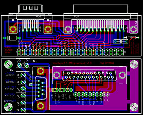
The connection to the laser head is made by two cables, because I want to decouple the high-current LD and TEC drive lines from the highly sensitive temperature sensor lines. I designed for this two interface boards for using standard D-Sub25 and D-Sub9 connector cables. At the laser head side, the card is put directly on the 30 pins of the laser head, and at the controller side the connectors go to a front plate of a simple 19'' rack. These interface boards are also handy by themselves, for use as test adapters for the 315 laser head.
Downloads: schematics, printed circuit boards and software
As a rule, the various bypass capacitors (0.1 and 1-10uF) in the schematics are only sketched and do not match precisely those on the PCB's; just use the locations as indicated on the PCB's. As another rule, all components are mounted conventionally, ie through-hole on the bottom (blue) side of the PCB's except for the few SMD devices, which are the integrated circuits, the inductors and the sense resistors on the TEC boards which go on the top (red) side. Moreover, on the LD driver board the WLD3343 and the voltage references go on the bottom (blue) side, while all other components go on the top (red) side - this is because of the limited height of the WLD3343 which means there is little space between the heat sink and the PCB. The white print on the PCB's goes on the top (red) side.
The PCB files are in Eagle .brd format, and can be processed/modified-to-your-needs with the free demo version of Eagle. Some board houses accept these files as-are, otherwise you need to export to Gerber format, etc. I use Olimex in Bulgaria which is cheap and fast, and with which I am very happy.
A zipped archive with the LabVIEW program, complete with the C-sources for driving the various ADC/DAC chips via the IOWarrrior24 USB interface is here. The "CIN" module compiles as-is under Xcode /OSX10.3, and needs to be modified if one wants to compile it under that other, less common and not so mature Unix OS, or Windows. This is for LabVIEW 7.0 but due to requests I have also included a copy for LabVIEW 6.1.
If I would build this again, I might do the following differently:
Return to home page