USB interface board using IOWarrior chip
Return to Compass 315M controller page
Return to home page
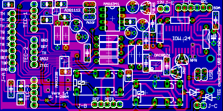
The analog-digital USB consists of an ADS1112 16bit ADC and DAC8574 16bit DAC (available as samples from TI), plus a MAX1238 12 bit ADC for less-critical voltage measurements (DAC output verification, TEC currents, setpoint temps), plus a MAX6341 4096mV precision voltage source which serves as an ultra-stable system-wide reference. There is also an I2C bus output that connects to the laser diode driver board ADC/DAC's. The I2C bus is interfaced to USB by a IOWarrrior24 chip which allows for direct hookup to a computer.
The 16 bit temperature resolution gives a better fine control, while the12 bit resolution I used before is borderline - already a change of one step of KTP drive voltage produces a considerable change in output power (12bit correspond to 4096mV, so one step corresponds to 1mV, which amounts to approx 0.03 degrees; 16bit improves this by a factor of 16, so the resolution would be roughly 0.002 degrees). On the other hand, it turned out that the resolution of LD and cavity temperatures need not be that high at all, 12bit is more than enough - see the measurements page.
Moreover there are two relays on the board that switch from digital to manual control mode, in which the TEC's are controlled by external 10-turn potentiometers. These should be eventually set to the optimal values found with the digital machinery. Actually I found that 10 turns is still too crude for accurate adjustments, so one needs extra series resistors for the pots for narrowing the adjustable voltage range, like to down to 10:1. This can be done of course only after the optimal voltage setpoint values are approximately known, and the values of the extra "range squeezing" resistors need to be determined accordingly.
For the schematics, see here. J-A (10 wires) connects to the laser head interface board, while TEC-1,2,3 (5 wires ea.) connect to the laser diode, KTP and resonator TEC controller boards, respectively. J-B connects to three front-panel 10-turn potentiometers for manual, computer-less control mode (extra series resistors not shown). J-C connects to a relay on the laser diode driver board, for switching between manual and computer control of the LD current. J-D has some extra digital outputs (eg for controling a shutter for holography), and has also a I2C bus output for connecting with the laser diode driver board (for digital current control). J-E connects to a 10-24V low power supply, and the USB connector (interfaced to the IOWarrrior24 chip) allows for direct hookup with a computer. To avoid analog-digital interference, the 5V for the IOWarrrior24 and the relays are taken from the USB bus (approx 150mA). With disconnected USB bus, the circuit automatically runs in manual mode. Finally, ADDR denotes some pins for setting the I2C address of the ADS1112 (not really necessary; the software refers to the jumper setting as shown).
A zipped archive with the LabVIEW program, complete with the C-sources for driving the various ADC/DAC chips via the IOWarrrior24 USB interface is here. The "CIN" module compiles as-is under Xcode /OSX10.3, and needs to be modified if one wants to compile it under that other, less common and not so mature Unix OS, or Windows. This is for LabVIEW 7.0 but due to requests I have also included a copy for LabVIEW 6.1.