Return to sale page
Return to diode laser page
Return to home page
Profiting from my investigations I designed a driver board that combines diode and TEC drivers, making use of certain high quality parts (like precision bulk metal foil resistors) that I have collected over the last couple of years. The result is a very stable, low drift and low noise driver module that allows to run suitable single mode laser diodes for hours without mode jumps.
The circuit is a combination of a highly stable, low noise diode driver and of a TEC controller based on the HY5600 module, plus an extra PWM circuit for reducing the power dissipation of the linear TEC driver to a minimum. It uses an L5973D PWM stepdown chip and the circuit is like the one on the data sheet. I added extra filtering in order to further suppress the ripple and noise. The diode driver is designed to handle up to 250mA. For external control, the two jumpers that connect the inputs to the trimmers can be removed.
I used SMD components on the board to save board size and thus cost whenever suitable, however some components had to be large, like the precision resistors. The layout had to be done carefully in order to realize the highest possible stability and low noise, in particular to avoid noise from the PWM part of the circuit being fed into the diode driver.
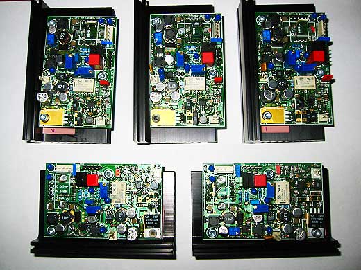
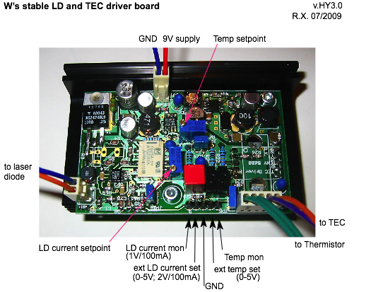
There are so far three versions of the boards. Version HY2.0 is used in the laser heads (with separated PWM controller), and versions HY3.x have the PWM controller included and are otherwise quite similar. Here is how they look and how they are hooked up:
Specifications
Operating voltage: 9V (12V max with higher dissipation),
typ current 0.5A, peak < 1A, fast 1A fuse advised (v3.2 has fuse included).
50Hz ripple should be less than approx 20mV; a LM317 or 7809 style preregulator should be doing fine.
High frequency ripple from eg., a switchmode supply, is filtered out.
Size without heat sink: 50x80mm
Heat sink 94x55mm or 99x55mm with M3 screw channels for easy mounting
Weight: 180g
Laser diode current: 250mA max (changeable)
Diode Voltage: 3V max @ 9V supply (changeable)
Laser diode noise: <1uA (below measurement limit)
Current monitor: 1V/100mA
Control voltage when in external mode: 50mA/V (0 - 5V)
Soft start: ca 10ms
Various diode protection features
Thermistor type: NTC with 10K @ 25C
TEC current: 1.6A max
TEC voltage: 2V max (variable for v HY3.2, via the extra trim pot. Be careful to not overload the HY5600!)
recommended TEC size: 1703 style, 15x15-20x20mm
PWM ripple: <10mV
Temperature drift at constant ambient temp: as good as 0.001C in 1h (with optimal mechanical design)
Short term temperature fluctuations: approx 0.0002C (with optimal mechanical design)
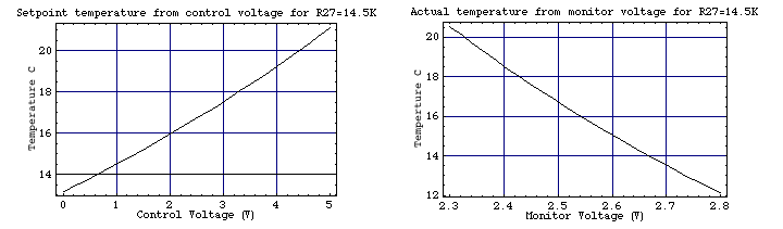
Temperature monitor voltage: 2.2 - 2.7V corresponds to approx 21 - 13C
Temperature control voltage when in external mode: 0 - 5V gives approx 13 - 21C
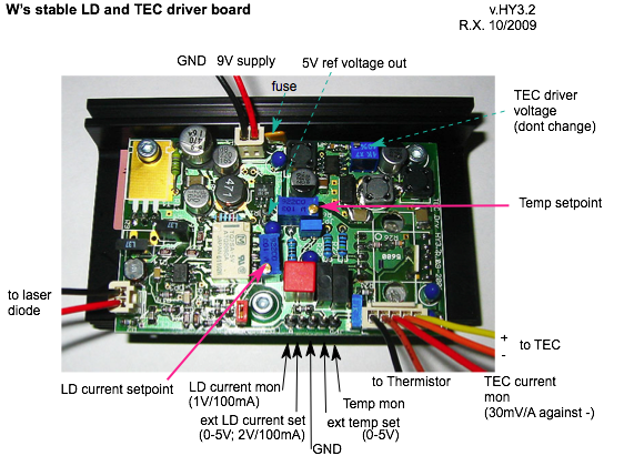
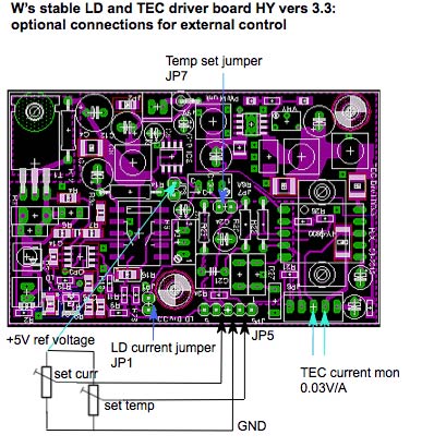
Extra features of v HY3.2 (see pic above): fuse, access to 5V reference voltage, TEC current monitor (30mV/A), max TEC regulator voltage variable by trim pot. It should normally not be changed from the nominal 4V setting. If there is long cable to the TEC one might slightly increase the voltage so that the maximum current of approx 1.6A can flow. Be very careful when adjusting that in order not to exceed the maximal power dissipation of the HY5600!
External control is possible by removing one or both jumpers (JP1,JP7) that connect to the diode current/temperature trimmers, and making use of the pin header "REF". One may connect external pots by connecting their wipers to JP5 and their end points to the ground and ref voltage pins, the the pics below. The pots should have 5-20K or so.
Note that this may compromise temperature stability, unless multi-turn wirewound pots (like eg a Beckman 7280 helipot) are used; they have a very good tempco, actually better than the trimmer pots. Note also: putting external pots may endanger the laser diode, if its rating can be exceeded by the max current (no danger for the 1W Nichias, though). In particular, wrong wiring may have the diode run at full current; it is strongly advised to test before with a dummy load!
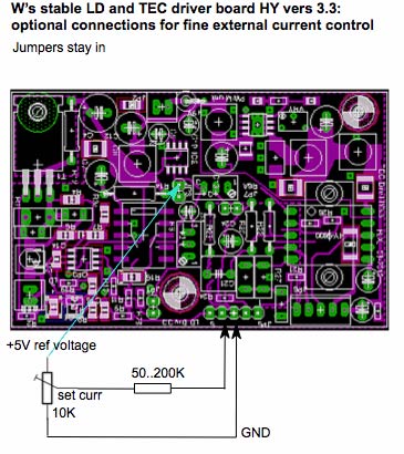
I would recommend to only use an external pot for the current and set the temperature once for all internally.
Further details and measurement data can be found at the respective pages for the diode driver and the TEC controller.
Each board has been tested and burned in for at least 24h. Nominal settings are 50mA diode current, 1500mV TEC control voltage (yields appr 15C), and 4V TEC driver voltage. I can supply also a suitable peltier element that fits to the board, plus thermister, for self-cost.
Vers 1.2 09/2010