Return to diode laser page
Return to home page
Inspired from the LD1255 Thorlabs driver (and the low-noise driver discussed here), I cooked up a (substantially modified) circuit that should have as least as good specifications, plus have some further advantages like a single voltage power supply. Moreover, having the diode mounted with the case to ground is much safer rather than having it connected, as unfortunately seen so often, to the plus supply (which puts the diode at great risk; not only would it instantly die upon the briefest short between the diode mount and ground, but it is also in danger from capacitively coupling in ESD via the floating diode mount).
Here the circuit I was converging to:
(link to newer, minimally different 375/500mAVersion 4.1).
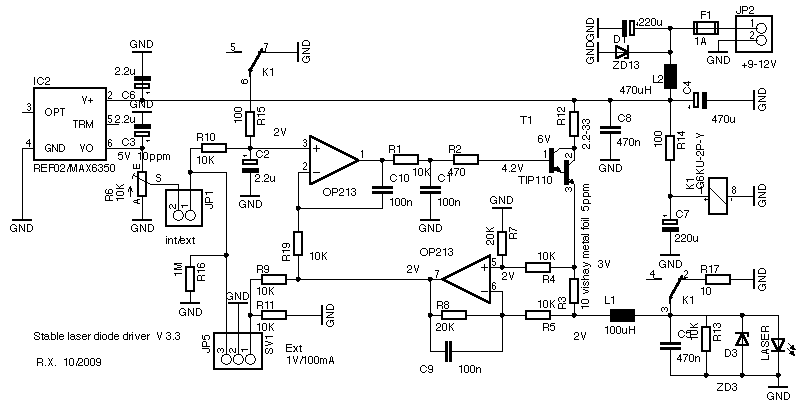
The circuit is fairly standard. The diode current is sensed by R3 and fed back via a difference amplifier to a comparator which compares the signal with a highly stable setpoint voltage which can be adjusted by R6 or fed in externally; the output is then input to the power Darlington transistor T1 which acts as an emitter follower current source. The voltages refer to typical 100mA operation, the circuit as-is can do 250mA, but by reducing R3, R12 it can do substantially more, like 2 amps (R3 then should be an Ohm, say). Good heatsinking of T1 is then a must.
As for protection, the diode is shorted by a relay when there is no power, and when power is switched on, the relay opens after a few milliseconds delay so that the rest of the circuit, ie, the op amps, has time to get into a well-defined state beforehand. It also softly ramps up the current by opening a second contact on the opamp input side. The relay opens after 7ms which is sufficiently longer than the settling time for circuit, and only after these 7ms the current starts to ramp up gradually. The is no sign of spike or oscillation during start and turnoff. The supply line inductor L2 (470uH) together with the buffer cap C4 suppresses transients and smoothes out sudden voltage variations so that the circuit can catch up regulating it. Moreover, R12 should be adjusted so that for given supply voltage (like 9-12V) the maximally possible current through the laser diode is limited to an allowed safe value (eg 180mA); some little cut and try may be necessary, depending on the precise forward voltages of T1 and the diode. That applies even more so when running blue ray 405nm diodes that have a higher forward voltage.
The 3V Zener at the output is not intended to protect the laser diode from a power spike, as one might have tought (it wouldn't help), but it protects the diode in a different way: imagine the Zener is not there and the laser diode while under power gets inadvertedly disconnected (eg briefly due to a bad contact in the connector); then the drivers ramps up to full voltage, like 8V, and charges up the output filter cap. The moment the connection is restored, there will be a current spike through the diode, which likely kills it. The Zener reduces the open circuit voltage to a safer value (when driving a blu-ray diode, the Zener voltage must be of course adapted). A Lasorb or a large ceramic cap parallel and close to the diode, which I use too (see below), helps as well in this respect.
The 375/500mAVersion 4.1 of the driver runs on 12V and is intended for the blue Nichia diodes and has R12 and the Zener D3 omitted, the sense resistor R3 is either 6.66Ohms (375mA Version) or 5 Ohms (500mA Version), and correspondingly R11=30K or open, resp. Moreover the inductors were changed such as to support the higher current.
The key to stability is in the components, I use a low drift and noise op amp OP213 and voltage source MAX6250 or MAX6350 and precision resistors, in particular 10ppm/C Vishay bulk foil resistors (these or these) for the shunt and highly stable 0.1% TNPW resistors around the lower op amp. With some reduction in stability one can also use cheaper and easier available parts; most critical is the sense resistor R3 which needs to be highly stable despite getting somewhat warm. The op amp which should have a small offset drift (say, around 1uV/degree or better), and low noise (around 1uVpp from 0.1-10Hz, say). 1uV translates to approx 1ppm, so compared to the other factors, the op amp then won't be the limiting factor. Some reasonable low cost choices currently on ebay are TLC2201 and AD822. A low cost voltage reference is REF02, which features around 10ppm/C and 10uV noise and is considerably worse than the MAX6350, but it is still tolerable in comparison to other factors hampering stability.
A weak point could have been the temperature coefficient of the trimmer R6, but I have performed careful measurements (see below) and found that while the overall resistance shows a tempco of like 100ppm, the drift largely cancels out ratiometrically: near center position the voltage drift is about 5ppm, which is fine. This refers to the 3296W style trim pots by Suntan that I use, which is the brand currently sold by Reichelt (this differs from what they say in their catalog, but the quality should be similar). I also checked the tempco of some other cheap, random pot of chinese origin I got via ebay, and found the tempco (as well as noise) much worse, like 50ppm.
So all-in-all, as for temperature drift we have as contributing factors (ppm=parts per million=0.0001%): 1ppm/C from the op amp, 1ppm/C from the voltage reference, 10ppm/C from the sense resistor, 5ppm/C (ratiometrically) from the feedback resistors, and 5ppm/C from the trim pot, which gives in total approx 20ppm/C (worst case, assuming no cancellations). Using the cheaper voltage reference yields approx 30ppm/C, which is still well below the design goal of 100ppm/C (ie., 10uA/C for 100mA diode current). As for noise, we have like 1uVpp from the op amp and1uVpp from the MAX6350 voltage reference (or 10uVpp for the REF02), plus an unknown amount from the resistors. So we will have at least a few uV (or more than 10uV) of noise, and this translates to a few hundred nA (or one uA, resp.) of laser current noise. As one uA corresponds to a laser frequency shift of approx 2Mhz, we see that the expected effect on the coherence length is not significant.
My measurements indeed show that (for the MAX6350 precision voltage reference) the regulation is 3uA per volt change of supply power, and the noise being less than approx 1uA at approx 100mA diode current. This is my measurement limit, and quite hard to do. On can also indirectly infer current noise from the laser line width seen by a scanning interferometer; with 2Mhz/uA line shift and a resolution of 5Mhz, one can check current noise down to a few uA).
This LD driver has been put together with my TEC drivers onto printed circuit boards described here and here.
Hookup of the laser diode:
If the connection to the diode is longer than a few cm, it is important to have a duplication of the protection circuit very close to the diode (like 2cm or so). This is to suppress induced ESR spikes, and also to filter out noise from the PWM part of the (TEC controller) circuit. Below it is sketched how to do it, notice also the grounding:
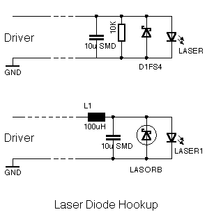
The top diagram, with a Schottky protection diode, shows sort of the minimum what should be done. The optimal setup is shown below: it uses a Lasorb device that yields superior protection, and also the extra inductor helps to keep away radiated PWM ripple; it is especially necessary if the diode head is connected by a long cable to the driver, along with the TEC power wires that do radiate a limited amount of noise (see below). I carefully verified that the driver is perfectly stable into the large capacitive load of 10uF. The 100uH inductor helps here.
Diode survival:
Despite I designed various protection features into the driver, the laser diode can still be killed if one is not careful. When hooked up there is little danger, apart from overdriving it and/or focusing the light back into the diode. But the critical part is the process of connecting it (connecting or deconnecting should always be done without power applied, see below). To ameliorite this, I have put an extra Schottky/resistor/cap combination directly at the diode mount. Still I managed to kill two diodes by connecting them to the board when not powered so that the output was short-circuited. Both cases happened for the same configuration, where there was a long cable going to an ECDL laser head with a large metal mass, which was not grounded. I assume this happened because, when inserting the two-pronged plug into the socket, the anode connection was inadvertedly made first, and the capacitance of the diode mount towards the rest of the laser head was sufficient to induce a large enough current spike (this may be called capacitively induced ESD). That's why I have increased the ceramic bypass cap to 10uF and also added a Lasorb for the more expensice diodes. To avoid this kind of problems, make sure that the laser head case is grounded (or better, connected to the driver ground) _before_ connecting the diode to the driver. And as a general rule, never fiddle with the connector when the laser is running, namely if there is a brief interruption of the current due to bad contact, there will be a current surge the moment the contact is good again. The 10uF cap/Lasorb combo is there to protect the diode in such a situation; the 3V Zener on the driver board helps to ameliorate this as well.
These plots show the issue:
Misc. Measurements:
Here some sample measurements, which were made for a couple of these boards, running under typical operating conditions (100mA LD current and 0.4A TEC current, unless noted otherwise):
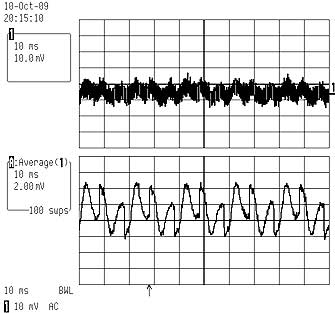
1) Noise
This is a noise measurement after a Burr-Brown 3630AM high precision instrumentation preamplifier with a gain of 1000, over a load resistor of 10 Ohms; thus one division corresponds to one uA. The sampled bandwidth was 0.5Hz-2.5khz.
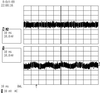
Top scan shows the amplifier's noise and the botton scan the diode driver at approx 200mA. There is a small 50Hz ripple due to the power supply. We see that over this bandwidth, the noise is less than one uA.
This is consistent with measuring the line width of a laser diode with a scanning interferometer:
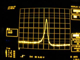
In this movie, the horizontal scale is approx 20Mhz/div, so the line width is at most approx 15Mhz which is the resolution of the interferometer. We conclude that the current noise is negligeable for our purposes.
2) AC ripple
This corresponds to the REF02C voltage reference, the MAX6350 is slightly better.
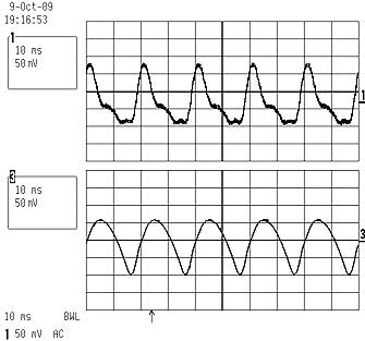
Top trace shows AC ripple of about 18uA which is out of specs. Bottom trace shows the reason for this, namely an improperly filtered power supply with a ripple of approx 160mVpp at 9V. The conclusion is that the power supply ripple should be less than approx 20mV in order to have an LD current ripple of less than 2uA.
3) PWM Ripple
While a measurement with the instrumentation amplifier of the 250khz signal is not possible due its limited bandwidth, one can however make use of the fact that the signal is periodic, so one can make it visible by averaging over a large number of samples. Here a result for the laser diode current:
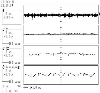
Top trace: AC voltage across a 10Ohm resistor, at max resolution of the scope. Seen is more or less the noise of the scope. Second trace: averaging over 200 samples, scale is 40uV/Div, which means an LD current 4uA/Div. Third trace: same with signal removed... this means that what is seen here and in the second trace is a measurement artifact. The conclusion is that the PWM signal is sufficiently suppressed. Fourth trace shows LD current ripple induced by feeding the current through the same 2m long D-Sub9 cable as the TEC. Obviously some of the TEC current ripple gets coupled into the LD line, and this should be avoided. So it is preferable to route the LD feed separately; but I checked that a small 100uH inductor right at the diode (together with a 10uF SMD ceramic cap across the diode), kills the signal sufficiently.
Next picture shows the voltage right at the TEC:
Top trace is raw data, bottom is averaged data; we see a PWM ripple of about 6mVpp.
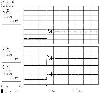
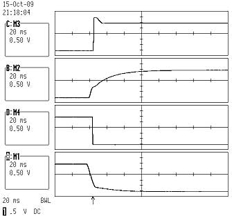
4) Turn-on/off
Top trace shows turn on to 200mA, hot-plugging in the diode to the running driver: some overshoot is visible. Second trace shows soft-turn on when applying power to the whole circuit; this is the safest way to power the diode. Next two traces show the same but for turn-off.
5) Trimpot temperature stability
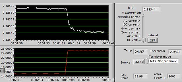
Top trace shows approx 150uV change of voltage at the Suntan trimpot (10K, wiper approx half-way of 4096mV total) under a temperature change of 10 degrees, which amounts to approx 5ppm/C ratiometric drift, and ultimatively to approx 1uA/C diode current drift which is fine.
Vers 1.6 09/2010