
1) Hytek HY5600 based linear TEC controller ("HY") (2008)
2) L5973D based TEC controller ("PWM") (2010)
3) improved LM2673 based TEC controller ("PWM-4") (2020, off-page)
Return to diode laser page
Return to home page
I got a bunch of Hytek HY5600 TEC contoller modules which provide a compact and easy solution for temperature stabilization. As per data sheet they are able to keep the temperature constant to 0.01 degrees, however it is not specified over under what conditions. Therefore I performed stability measurements myself and concluded that they are well suited for our purposes - see below. A downside is that they provide only unipolar rather than bipolar drive of the peltier element (ie they can cool only), and one has to rely on the (minimal) heating by the laser diode to counterbalance this. This means that the circuit won't be able to operate as intended for ambient temperatures smaller than the diode setpoint temperature. The latter thus needs to be in a relatively small window (say 14-17 degrees) because if the diode runs too cold there are problems with condensation of moisture. Another downside is that these circuits are not readily available, but since I got a load of them it would be a waste not to use them.
At first I had used a simple variation of the circuit in the data sheet, namely making the setpoint temperature adjustable by a trimmer potentiometer. The relevant piece of the schematics is as follows:
A temperature stability measurement of a first test setup looked quite reasonable:
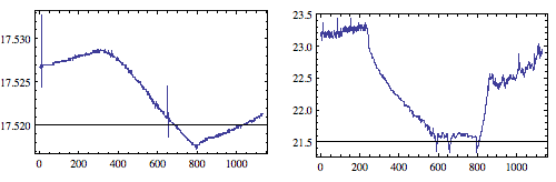
On the left is plotted the temperature of the diode mount, measured by an independent extra embedded thermistor (the diode was driven with 100mA current; I will specify the mount at a later time). The x-axis is in steps of 10 seconds, so spans like 3 hours. On the right is plotted the corresponding ambient temperature which was varied in order to provoke a drift. We see the temperature drifts approx 0.01 degrees for 2 degrees change of ambient temperature. This is not at all bad given that this was a first test setup, and shows that the controller is well suitable for our purposes (which demand a stability of like 0.01 degrees over the time of holographic exposure).
After minimally modifying the circuit, the following curves emerged:
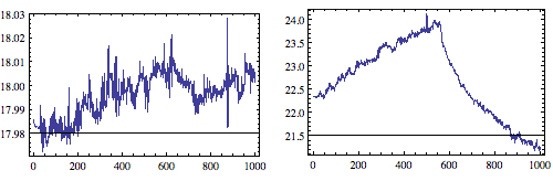
There is strong noise of the order of a few hundredths' of a degree, which most likely would ruin any hologram. Guess what the only change of the circuit was? I replaced in the setpoint voltage divider two high precision bulk metal foil resistors by a cheap 100K trimmer R6, that was all! I couldn't believe it at first and changed a few times back and forward, and yes the effect persisted. I also tried a few different trimmers, and for physical reasons a lower value of the resistance gives somewhat less noise but it was still bad enough.
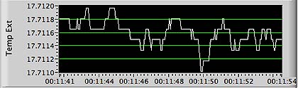
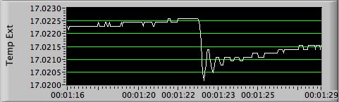
Here the effect in a slightly different format, directly captured off the LabVIEW interface, a comparison of the temperature when using a 10K trimmer (left) and the precision resistors (roughly 10K in total as well):
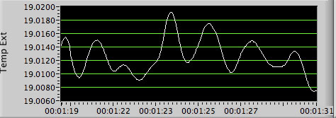
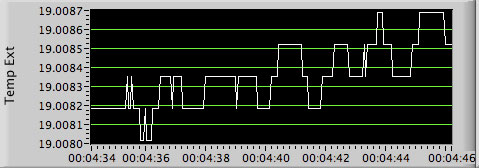
We see that just replacing the trimmer by low-noise resistors reduces the noise of approx 1/100 degree amplitude to a few 1/10.000 degree amplitude!
This state of affairs called for an improvement, and the complete schematics now is:
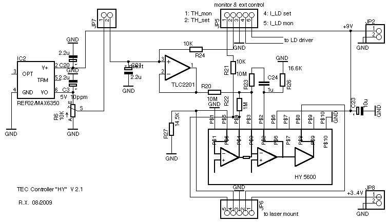
JP7 can be jumpered to either use the pot or external control. The opamp wouldn't have been necessary but I added it as buffer for external control. The feedback circuit R23/C24 is quite simple, I found this to work so well that a full-fledged PID element didn't seem necessary. R26 sets the current limit, which must be compatible with the maximal allowed power dissipation of the HY5600.
The idea was to reduce the influence of the trimmer by changing the setpoint voltage via introducing an offset to the second opamp in the HY5600. The 5V voltage span of the trimmer R6 then translates, via R20/R22, to approx 0.5Voffset voltage span, which captures a temperature range of approx 13..21 degrees C. This reduction has the desired effect to reduce the trimmer noise. Also the adjustment resolution is increased by a factor of 10, which is handy if one wants to use 12bit DACs for control. Said differently, in the first adjustment circuit shown further above, the 5V span translates directly to the thermistor voltage and so yields an enormous temperature range, many times larger than what we need and also much more sensitive to thermistor noise; the new circuit optimizes the adjustment voltage range.
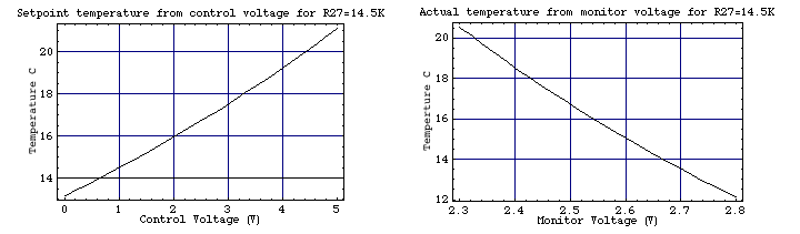
The new schematics avoids this and is much more stable; the temperature stability is mainly determined by R27, which is a (combination of) 5ppm bulk metal foil resistor. For the other resistors, their temperature drift largely cancels ratiometrically. Be careful to get for R20 and R22 50ppm resistors and not random ones, which can have 400ppm or more according to my meaurements). The value is not critical and simply determines the range for which one can set the temperature. Here is how setpoint and monitor voltages at JP5 are related to the temperature:
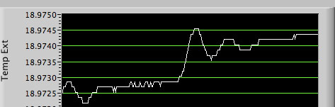
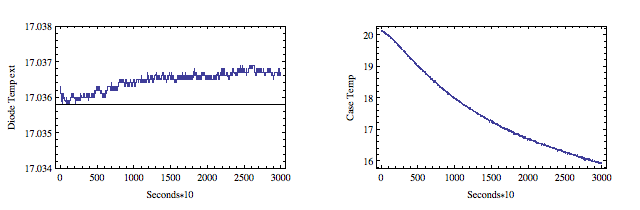
Here is a plot of the noise/drift over 10.000 seconds at stable ambient temperature:
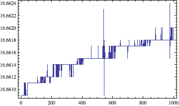
The apparent total drift is about 1/1000 of a degree with noise in the order of 1/10.000 degree - this is in the order of resolution of the measurement machinery and so the actual values should be at least as good!
The high temperature resolution is achieved by using a HP3478A (alternatively Solartron 7081 or Datron 1281) DVM with GPIB interface, measuring the resistance of an extra independent thermistor embedded in the diode mount. The resistance is measured automatically every 10 seconds, controlled by a LabVIEW program, and every other measurement is done for a 1ppm high precision resistor to determine instrument drift and compensate for it.
Here now the effect of changed ambient temperature:
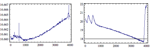
The yields approx 0.005 degrees for a 2 degree ambient change, which is fine. Note that this is for the combined system in realistic operating conditions, including the diode running at 100mA with my LD driver.
Last not least here the response under changing the supply voltage from 9 to 10V (using a MAX6341 precision voltage reference):
So 1V change amounts to approx 1/1000 of a degree which is just fine.
This TEC controller has been put together with my LD driver onto a printed circuit board described here.
Since I was running out of the HY5600, I was designing from scratch a new highly stable controller. It performs at least as good as the HY5600 based one and can supply more power; the intended application is the blue Nichia diode. It uses the proven L5973D PWM stepdown chip that I used to reduce the supply voltage to the HY5600 chip; the main modification is that now this chip feeds the TEC directly and is controlled by a PID control loop that has been optimized for the intended heat load (in particular ECDL setups).
Many other chips can be used that have a connection to the output of the internal voltage comparator (this pin is used for compensation and thus often called "comp"); however many of the very modern chips don't have this pin, so one needs to check. Other examples for suitable chips are the L-series of ST, like the other L597x, or the L4973D3.3, which can deliver up to 3A; one thing to care about is that often the feedback and/or compensation pins have some extra control functionality built in, and this may interfere with our purposes. Best is if these pins just behave as opamp inverting input and outputs.
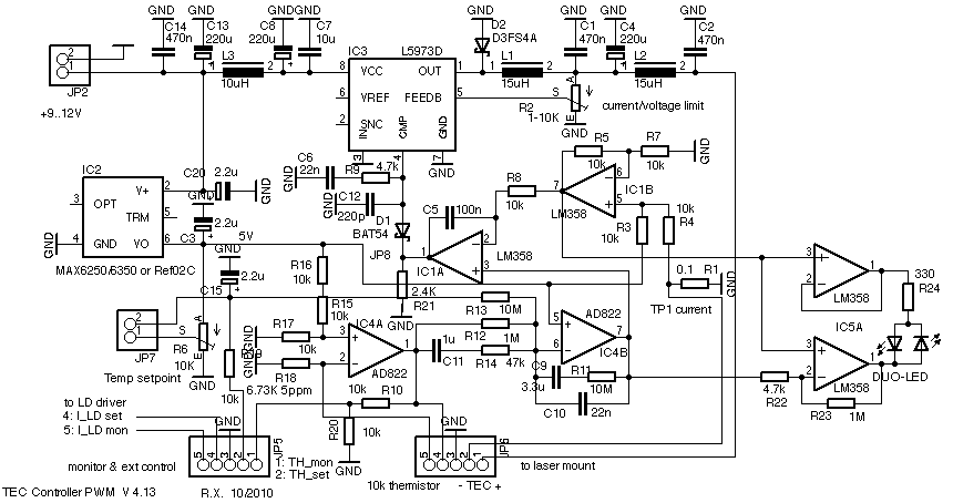
The circuit is as follows:
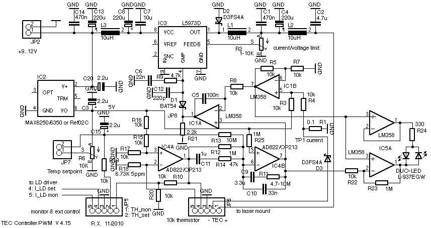
(minimally different older version 4.13)
It works as follows. IC3 is the PWM regulator, whose input and output are heavily filtered in order to minimize switching noise. It is controlled by three feedback loops. The first is the standard one via the feedback pin, and sets the maximal voltage or current via trimmer R2. The second loop sets the current via the current sensor R1, the level shifter IC1B and the comparator IC1A, and acts on the PWM controller by pulling the compensation pin down via the Schottky(!) diode D1. R21 helps to pull the voltage down enough for completely shutting off the L5973 when it is supposed to be so. I may drop the second loop and IC1 at some point, since one could do without, but for some convenience reasons I kept it so far. The third loop is the primary loop, it senses the temperature by the 10K thermistor, then uses IC4A as precision comparator and IC4B as PID controller, and acts on the current loop via IC1A. IC5 provides a simple way to display "too hot" or "too cold" via a duo (red/green) LED; the LED goes off when the temperature is (close to) locked.
Note that the PWM controller shuts down below approx 0.6V of output voltage, so it requires a minimum heat load to regulate properly. The heat generated by the laser diode is normally sufficient, unless the ambient temperature is too low (it should be not less than a few degrees below the setpoint temperature). D3 helps to ameliorate this by reducing the minimal output voltage to approx 0.3V, and if one wishes to keep regulation to close to zero current, one may add another diode in series to cut down the output voltage (at the expense of reduced efficiency). Using a TEC with higher resistance (a few Ohms) is also beneficial in this respect.
The temperature stability is mainly determined by R18, which is a Vishay bulk metal foil resistor with a stability of 5ppm/C. The thermistor voltage is compared to the voltage divider R16,R17,R18, which are 10ppm/C TNPW resistors for which the temperature dependence mostly cancels out ratiometrically. For the other resistors around IC4B, the temperature drift largely cancels as well, but be careful to get 50ppm resistors or better. I ran some tests for R12 and R13 I use to verify that they have a low Tc (approx 25ppm of the same sign; the metal film resistors sold by Reichelt do well). IC4A and IC4B are low drift low noise opamps of type AD822, which amount to like 2ppm/C; many other low drift/low noise types, such as the TLC2201 can also be used (note that for FET amplifiers R25 is not necessary, but for other opamps like the OP213 it cancels the bias current which otherwise induces a suprisingly strong temperature dependence). The temperature setpoint is chosen by R6, and the same stability/noise considerations as for the HY5600 as described above apply here. Jumper JP7 allows to disable the trimmer and use external control.
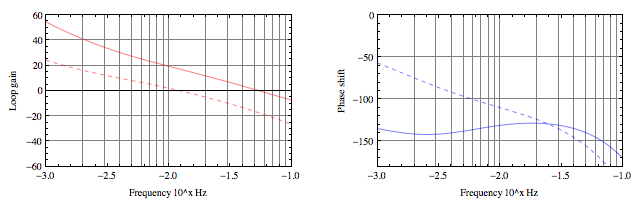
The main, high gain comparator is IC4B which compares against the ultra stable, low noise voltage reference IC2 (Ref02 can be used instead with little impact on stability). IC4B also serves as PID regulator, whose working is described here. For best stability, C9 and C11 must be unpolarized fim capacitors, like Wima type MKS. I optimized the loop for loads with relatively high thermal inertia, like base plates for ECDL, and features large gain with good stability; a drawback is that it undershoots the temperature by a few degrees at startup (due to maxing out the integrator), so that it takes several minutes to stabilize. For other loads one may need to modify C9, R11, R12 or more. If for light loads the loop oscillates, reducing R11 by a factor of two is the first thing to try (for large loads 10M is fine, for small diode mounts I found 4.7M suitable).
Here are tte Bode plots for the control loop when driving a typical ECDL setup (the dashed lines correspond to the measured uncorrected, open loop without IC4B):
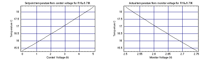
Below we show the calculated input control voltage and output monitor voltage versus temperature, for R18=6.73K (this particular value reflects parts that I have, and the circuit is designed to give a convenient temperature range. Other values are possible by also suitably changing R15-R17):
This TEC controller has been put together with my LD driver onto a printed circuit board described here. Much care has been taken for the layout in order to provide maximal thermal stability and minimal PWM noise.
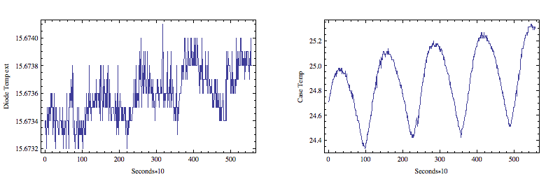
My measurements how a few mK drift over extended periods of time, and short-term noise fluctuations of like 0.2mK; that requires a good mechanical design and thermal shielding of the thermal load. Below, to the left shown are the short-term temperature fluctuations with a heat load that is quite small and with non-optimal thermal shielding; the fluctuations are a few mK (still tolerable for holography applications); to the right, a larger load was used and better shielding, and the fluctuations were reduced by a factor of approx. ten:

Here a long-term temperature stability test of a complete 445nm laser head running with 250mA diode current, under varying ambient (case/heatsink) temperature (after 1h warm-up time):
The test was conducted with my new Datron 1281 DMM which has like 1ppm/C temperature stability. The total drift within 8h was less than 1mK, which is negligeable. Since the case temperature changed by 4 degrees, we have an overall temp dependence of approx 0.25mK/C, which amounts to a temperature stability of approx 14ppm/C, which is an excellent value. However, heating and cooling the driver separately gave a higher temperature dependence, in the order of 30ppm/C. This is shown in the following plot obtained by placing the driver in a sealed box put ontop of a room heater:
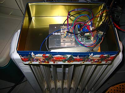
It is quite difficult to obtain reprodible results, since there are cancellations of temperature coefficients (eg in voltage dividers made from equal resistors); for these cancellations to take place, requires the same temperature for all components, which however have different locations. So in order to have maximal stability, one should enclose the driver so that no air drafts can hit it, and put it on a large heat sink (so that temperature variations will be slow and can even out). Here a pic of my test setup (where the metal box is closed during actual measurements):
Here a plot of the temperature of the diode mount, when the supply voltage for the complete board of 12V was reduced by 1V, while the diode was running at 300mA. It was made with an independent embedded thermistor :
We see a change of 1.5mK, which is pretty good; also the PID loop response settles quite fast.
Here a movie of the display of a my scanning interferometer, showing the spectrum of a blue Nichia diode at high resolution:
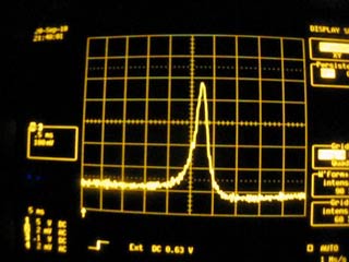
The horizontal scale is approx 20Mhz/div, so the line width is at most approx 15Mhz which is the resolution of the interferometer. This corresponds to a coherence length of several tens of meters. We conclude that the short-term temperature and current noise of the driver is negligible for our purposes.
Return to home page
Vers. 2.7 -12/10