Return to home page
This tiny inexpensive device is quite stunning, and with reliable 70-100mW single longitudinal mode operation at 530nm it beats out, at least for the amateur holographer, much more expensive green lasers such as argon ion lasers and Coherent Compass lasers. So naturally it is interesting to investigate these little beasties in some more detail. Thanks go to George S. and Dave B. for providing me a few samples of these.
Also, thanks go to members of the holography forum for useful informations and inspiration. Most relevant info can be obtained there, and I will add here just a few extra notes and observations from my perspective.
First off, the data sheet of the PL530 can be found here, and a good background read about how it works is this.
3) Laser mount
For the "White Light Engine", which is a RGB laser module of certain Pico projectors which contains the PL530 besides red and blue laser diodes, see here.
What is important for the holographer is to identify and maintain an operation spot where single mode emission is stably maintained, without mode jumps over time. The relevant parameters are the diode current, I_LD, and the PPLN heater resistance, R_H. The latter is most crucial in that it needs to be fine tuned and kept very stable.
The case temperature is not very critical but it appears it should be kept low and relatively constant, say at 18C. So three drivers are necessary, one for the laser diode at about 500mA max, one for the PPLN heater at about 80mA, and a TEC driver for the peltier element against which the PL530 case is press-mounted (or glued with thermal adhesive). Running I_LD > ~480mA or I_H>~80mA can instantly destroy the device, so precautions need to be taken.
The data sheet mentions that the limiting factor for the PPLN heater is the resistance R_H, and the allowed maximum is given by R_H=1.27*R_25, where R_25 is the resistance at 25C. The datasheet doesn't state clearly the conditions for which this applies, I assume R_25 is determined for vanishing heater and diode currents, and R_H is defined for the actual operating conditions (does anybody have the application note "Heater Control & Driving" as mentioned in the PL530 data sheet? Nowhere to be found...).
Thus the first thing to do to with a new device is to measure R_25, as it can widely vary between 27Ω and 37Ω. The samples I got so far lie all around 28-30Ω, so one should keep R_H<36-38Ω for these.
From this it is clear that what needs to be kept constant during operation is the PPLN heater resistance, which acts like a PTC thermistor. Feeding it eg. with constant current can lead to a destructive runaway, in that if the resistance grows due to heatup, then due to P=I^2R the dissipated power grows too, and this makes it heat up even faster. So the right thing to do is to use a bridge circuit that stabilizes the resistance and not the current, as mentioned in the data sheet.
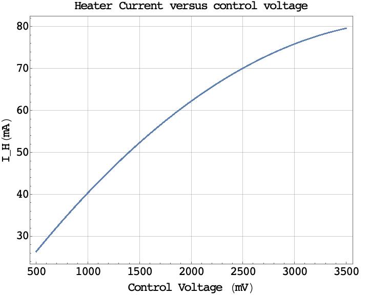
On the other hand, changing the resistance setpoint also changes the current, so monitoring the current is still a good way to label the operating point when all other parameters are fixed. For the first device I tested, I found the following relationship:
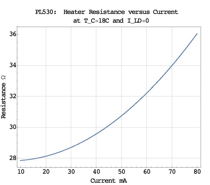
This is just for orientation, it will change between different devices and also for actual operating conditions when there is thermal input from the laser diode. The take-home message is that the current should be kept below of about 80mA, at least for the samples I got.
Here is a plot of the output power as a function of the heater current, where discrete jumps reflect transitions between different mode structures:
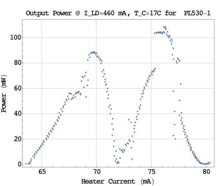
When adjusting one finds that there is some lag due to thermal inertia, plus hysteresis (ie, when going up and down the modes don't switch at the same current). This can make the adjustment a bit cumbersome and one needs a very fine control, ideally by a multi-turn potentiometer. This should be easily accessible because due to long-term drift the optimal setting (slowly) changes over time. One aims for the spot with maximum power as single mode operation is most likely there, and this cannot be achieved accurately enough by the naked eye only - one really needs some meter to monitor the power.
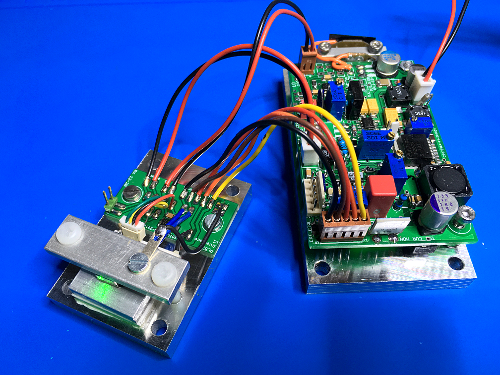
Below is a picture of a fully assembled laser, which has extra collimation optics attached to the PL530. Linked to is a movie of a test setup that shows clear single mode operation at 94mW, and also how very slight adjustment of the heater current changes the spectrum:
 (click for movie)
Since my old LD+TEC driver board was at about its limit when driving the PL530, I decided to revamp it and optimize it for the PL530. Which means a board with an LD driver that can easily handle 500mA while keeping highest stability, a TEC driver that can handle 1.5A or so without running hot, plus a driver for the PPLN heater. This allows to run the PL530 for hours without a mode jump.
The board is in fact more stable than needed to operate the PL530. Thus cheaper components could be used if one wants to just run the PL530. The reason for the better-than-necessary design is that it can run also lasers with more stringent stability requirements as well, eg. high power ECDL's.
Here is the schematics of the TEC driver:
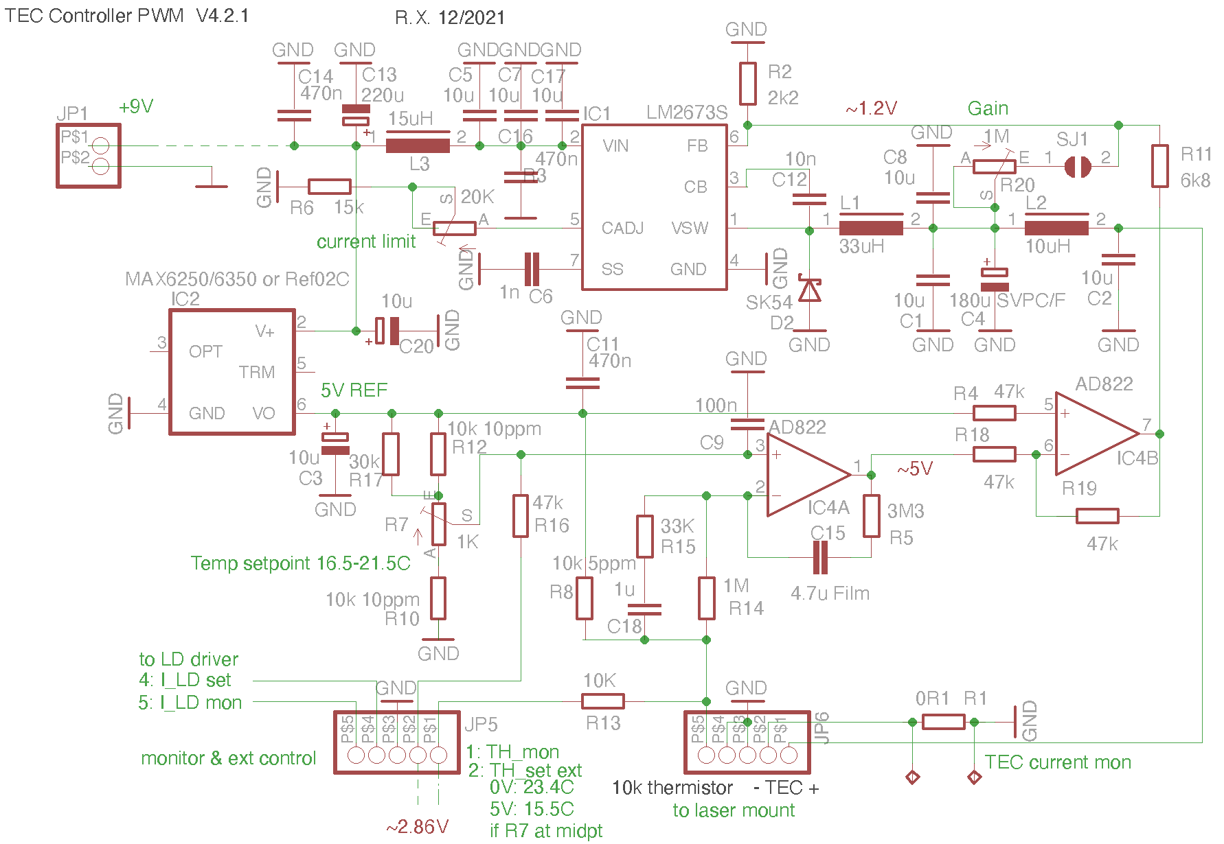
It is crudely based on my previous design, but is more powerful (max ~2A) while being highly stable and having low noise. Switching noise is minimized by generous filtering and careful PCB layout. At a typical TEC current of 300-600mA nothing heats up noticeably. Design features include an adjustable current limit, adjustable loop gain, adjustable temperature of about 16.5-21.5C and interface for external control. The PID loop is optimized for a sandwich press-down mount of the PL530. The solder bridge SJ1 in the feedback loop should normally be closed, but can be temporarily opened for trouble shooting.
Here is the diode driver:
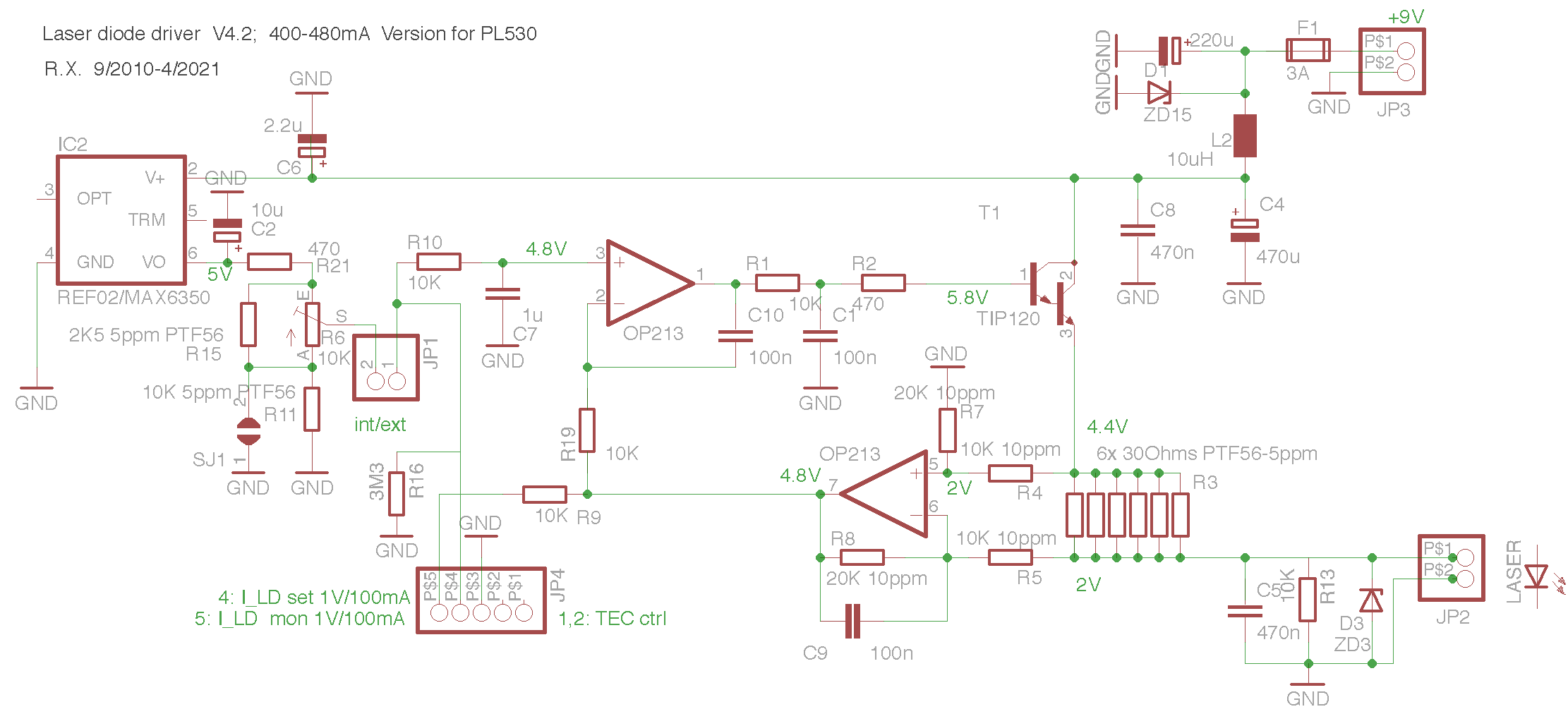
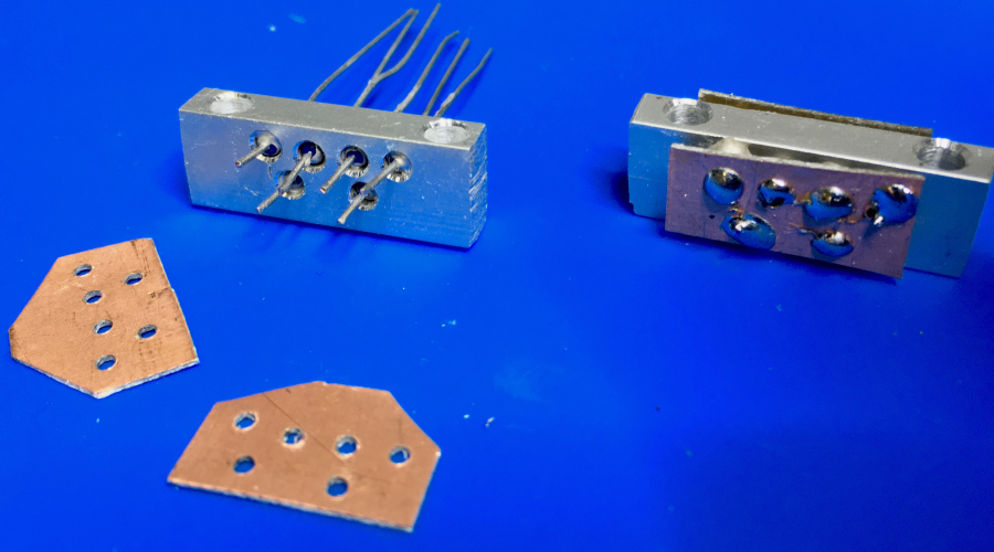
It is a minor, higher power modification of my old-n-proven driver described here. The main difference is the current shunt resistor. Since I was running out of my Vishay bulk metal foil resistors with extremely low temperature coefficient, I had to find a replacement. In the end this was a bunch of 30Ohm PTF56 resistors with 5ppm/C. Since 5Ω at 0.5A produces too a large heat load on the PCB for good stability, I decided to mount the bunch of six resistors separately on a heat sink. See the picture below for an idea. Also I restricted the range of the trimpot to cover only the top range 400-480mA, which reduces the temperature coefficient considerably. In effect the driver runs extremely stable even at 480mA which is the max of the operating range of the PL530.
For other diodes, R21, R15 and R11 need to be suitably adapted. Shortening SJ1 extends the range down to 0mA, shortening R21 extends it to 500mA. For lower currents the shunt R3 should be increased by removing some of the resistors; the max adjustable current is I=2500/R3 mA.
Finally, the PPLN heater driver is based on a ratiometric resistor bridge that stabilizes R_H. For this I took more or less the same as the nice circuit proposed here. At first I had trouble to make it work, since the current always shot up to the max. It turned out that due to mysterious circumstances the opamp AD822 I used got into an ill-defined, latched-up state upon start, and all was working fine by exchanging it by an LT1013 or OP213. So here is the circuit:
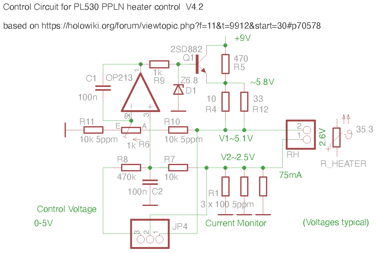
(Voltages are typical). The Zener diode D1 is to protect the heater from currents over about 80mA.The cutoff is determined by R4/R12, the default of which is 10Ω with 33Ω parallel to it. This works well for my batch of PL530's and cuts off at about 78mA and 36.5Ω of heater resistancet to be on the safe side. In particular the voltage divider R11-R6-R10 is adapted to these typical values. Given the possible large variation of the heater resistance, it can happen that the range adjustable by R6 is not enough, and in such a case one may put en extra 100k parallel to R11 or change the pot R6 to 2K. One may also need to adjust R4 by adding a further resistor in parallel to reach higher currents. It goes without saying that one should be extremely careful not to exceed the max specifications of the PL530, when playing with the heater current limits.
The board is set up to allow easy external monitoring and control via JP4, and a typical response (which depends on the setting of R6) of the current is:
The heater current I_H is easily monitored via the voltage drop over the resistor R1 (30mA/V), and by measuring the voltages V1,2 of pins 1 and 2 of JP4, one can easily determine the resistance of the PPLN heating element: R_H= 33 (V1-V2)/V2 Ω. This and not the current is the relevant quantity that needs to be kept constant.
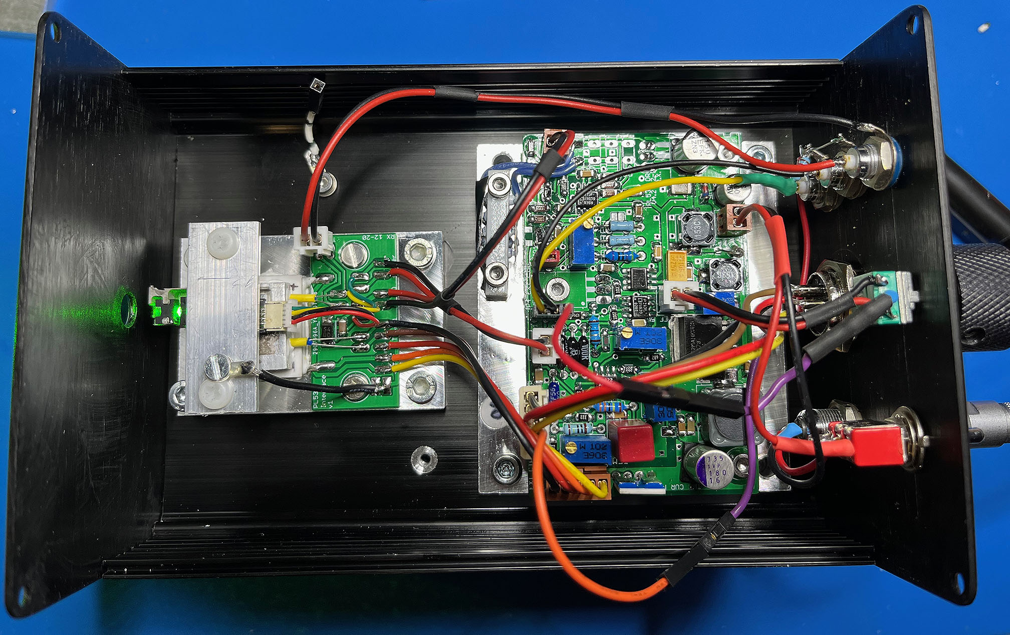
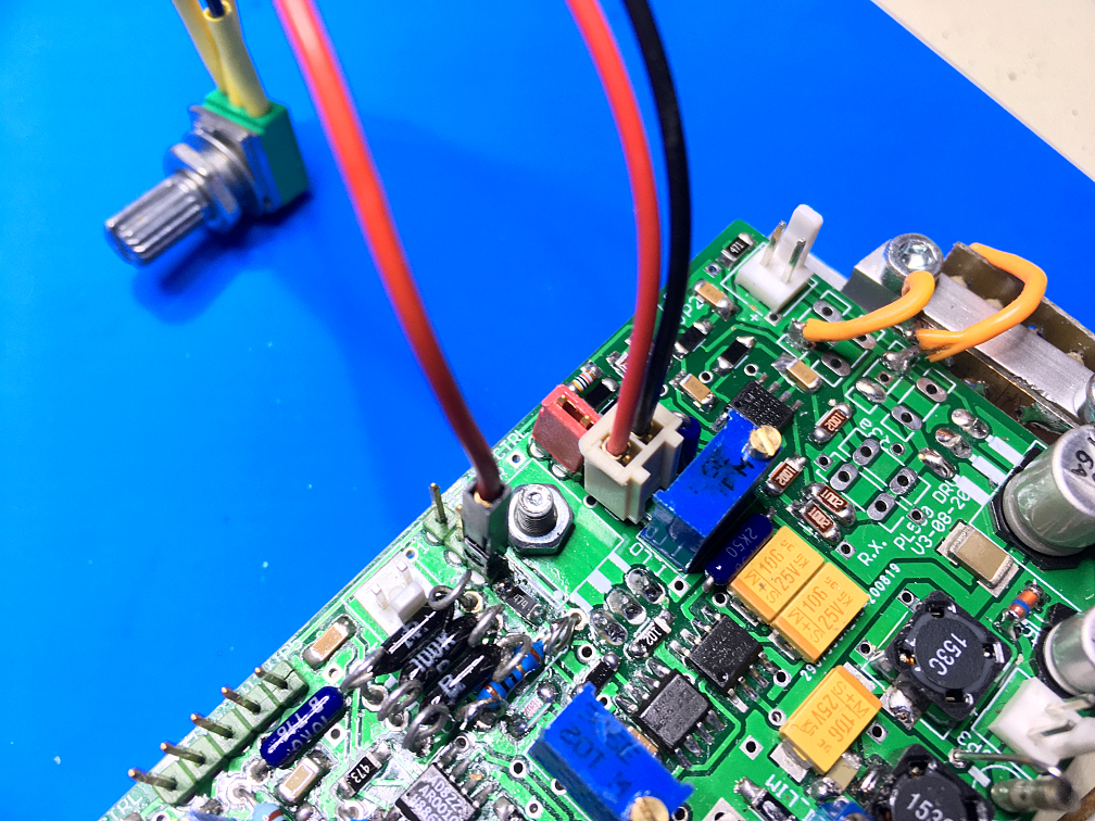
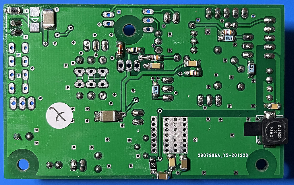
Now let us consider the complete system. Below you see the assembled board of the version 4.1 (and for reference, here and here the almost completed current board version 4.2):
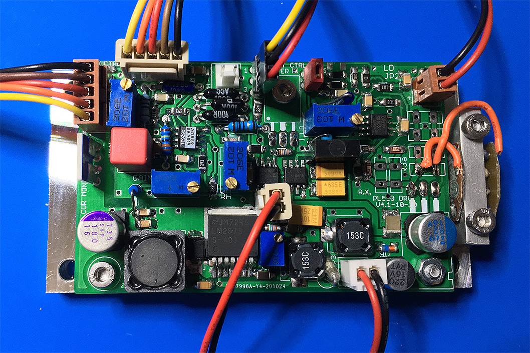
The external shunt resistor is on the far right. On the board there is also mounting space for bulk metal foil resistors in case one wants to use some of those instead. At the top-center you see the circuitry of the PPLN heater (I forgot to wire the PPLN heater for the pic, that's the empty white two-pin connector). The power transistors are mounted below the board against the heatsink plate. Most components are SMD, except for through hole precision resistors and the high ohm resistors of the TEC PID loop.
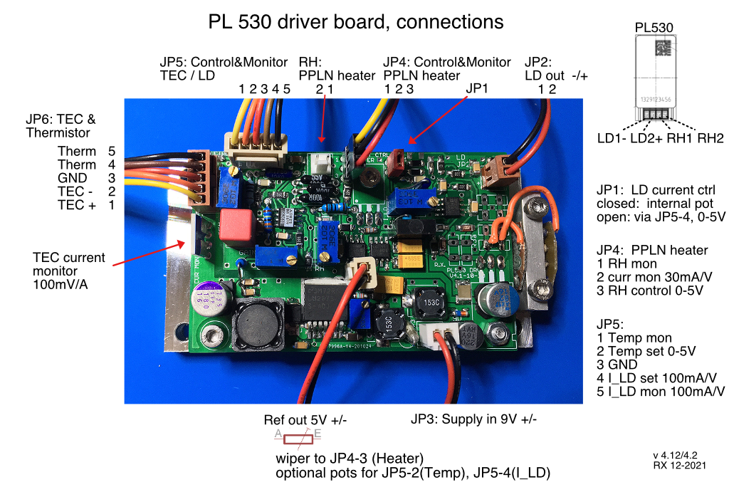
How to hook it up:
Connect the Peltier/Thermistor assembly to JP6, the laser diode with JP2 and the heater with RH, and of course JP3 to a 9V supply. Typical consumption is about 600mA at 19C ambient temperature. It will go up with the ambient temperature due to stronger cooling needs. Also, in the initial cooling phase, the current can be much higher. So altogether the supply should be able to deliver 1.5-2A, to be on the safe side. There is a 3A fuse on board, next to the supply connector. Be careful to avoid ground loops, especially if measurement equipment is connected. Ideally only one ground connection is made to the case (eg via JP-3 which should connect to the ground of the laser mount).
Pin 3 of JP4 should go to the wiper of an external 10k potentiometer, while Ref_out/ground go to the endpoints of the pot (note that Ref_out may not be short-circuit proof).
The other pins of the connectors JP4, JP5 do not necessarily need to be connected, they are optional for remote monitoring and control, and troubleshooting. The same applies to the TEC current monitor solder pads. See the pics below.
Above applies to versions v4.12 and v4.2, for v4.1 and below, JP4-1 and JP4-2 are exchanged.

(Note that for some boards the pots were inadvertedly put in the other way around, in which case the pot turns go the opposite way...)
The board comes with default settings: T_Case=18C, I_LD=470mA, and R_H/I_H around 35Ω/75mA (72mA in later versions). The actually needed settings for the heater will depend on the device. For this, only the external pot needs to be adjusted, for maximum power. The optimal spot is extremely narrow and hard to find without a power monitoring device. It can drift over time which is why the external pot should be easily accessible. A single turn pot is borderline ok for this. It is best to let the laser run for 1/2 hour or so until all is in equilibrium. Then the pot setting won't be needed to be readjusted any further. The other pots should only be touched if you know what to do (eg for a very different hardware setup the temperature control loop gain might be in need to be adjusted; for this monitor the TEC current by a scope connected to the solder pads and make sure that there are no oscillations).
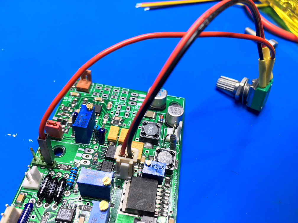
Here we show how the pot is connected to the reference voltage, for newer and older versions of the board:
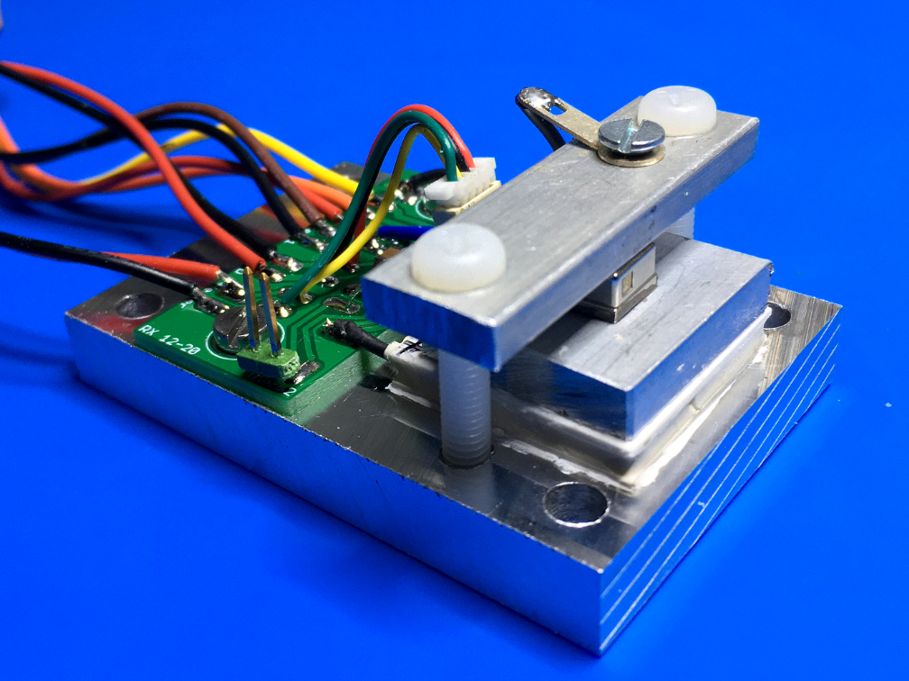
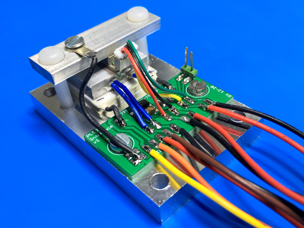
The mount of the PL530 is in line with my other temperature stabilized diode "press-down" type mounts. There is some laser diode protection by a parallel Schottky diode and 1uF cap, plus an extra independent 10K thermistor that allows to measure the temperature by a DMM independently from the driver board. Grounding is done carefully to avoid ground loops. The Peltier element is a TES1-07103 with about 2-3Ω. I tried to use a small 1mm 4-pin connector with the PL530 for easy interchangeability, let's see whether this was a good idea (the red/black colored wires are counter-intuitively swapped for the diode, which is already a bad omen ...)
Of course the whole assembly needs to be mounted on a heat sink, and it should be completely enclosed to avoid air currents when in operation. Relatedly, it is extremely important to avoid any kind of dust eg. coming off thermal paste or solder smoke landing on the tiny output window. Thus the PL530 needs to be added at the very last step and the whole thing must be protected from dust by all means, or your beam spot will be ruined soon. This applies even more so to laser diodes which tend to be much less stable against the slightest perturbations.
What is still missing is a way to attach a collimator lens/power sensor close to the laser to improve on the collimation. The White Light Engine, which is a RGB laser module of certain Pico projectors which contains the PL530 besides red and blue laser diodes, does feature excellent collimation, and for more info see here.
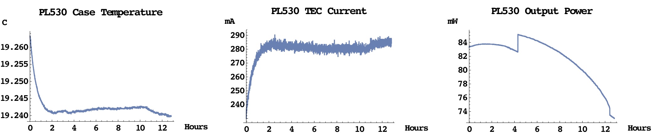
I conducted extensive measurements for these boards. Below you see long-term stability measurements in a room with constant ambient temperature:
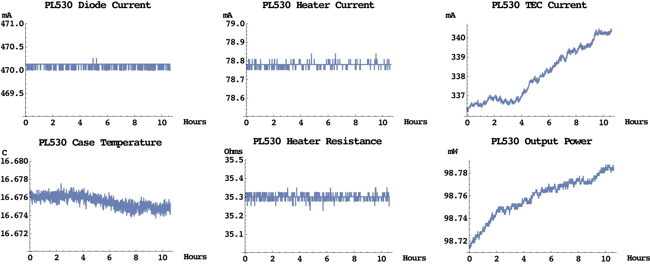
It is evident that there wasn't a single mode jump within 10 hours or so (they almost always come with a little jump in the power). We see a minimal drift in output power which is correlated with the case temperature and hence, with the TEC current.
On the other hand, below you see a mode jump after 4 hours past turn-on which is signified by the little jump in power:
Quite mysterious and troublesome where at first these instabilities:
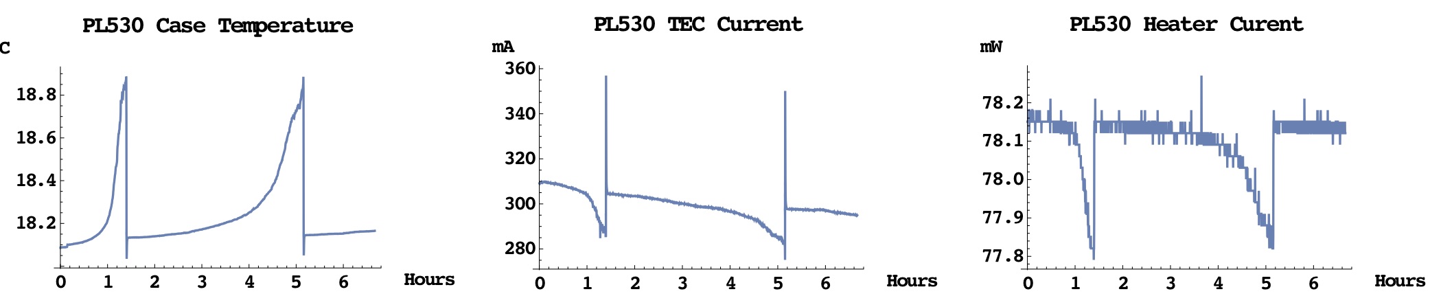
What was the reason behind? After some frustrating detective work it turned out that the plug to connector JP6, which had been often disconnected and reconnected upon testing procedures, apparently had a strained contact that sporadically screwed things up. Subsequently I used more firm connectors for the boards, and the problem has disappeared. Nevertheless one should avoid excessive plugging and unplugging of any critical connector as much as possible, in particular also the connector for the laser diode. Better not even touch that when the diode is under power, as a brief reduction of contact would ramp up the driver output voltage, possibly destroying the diode when the contact gets good again.
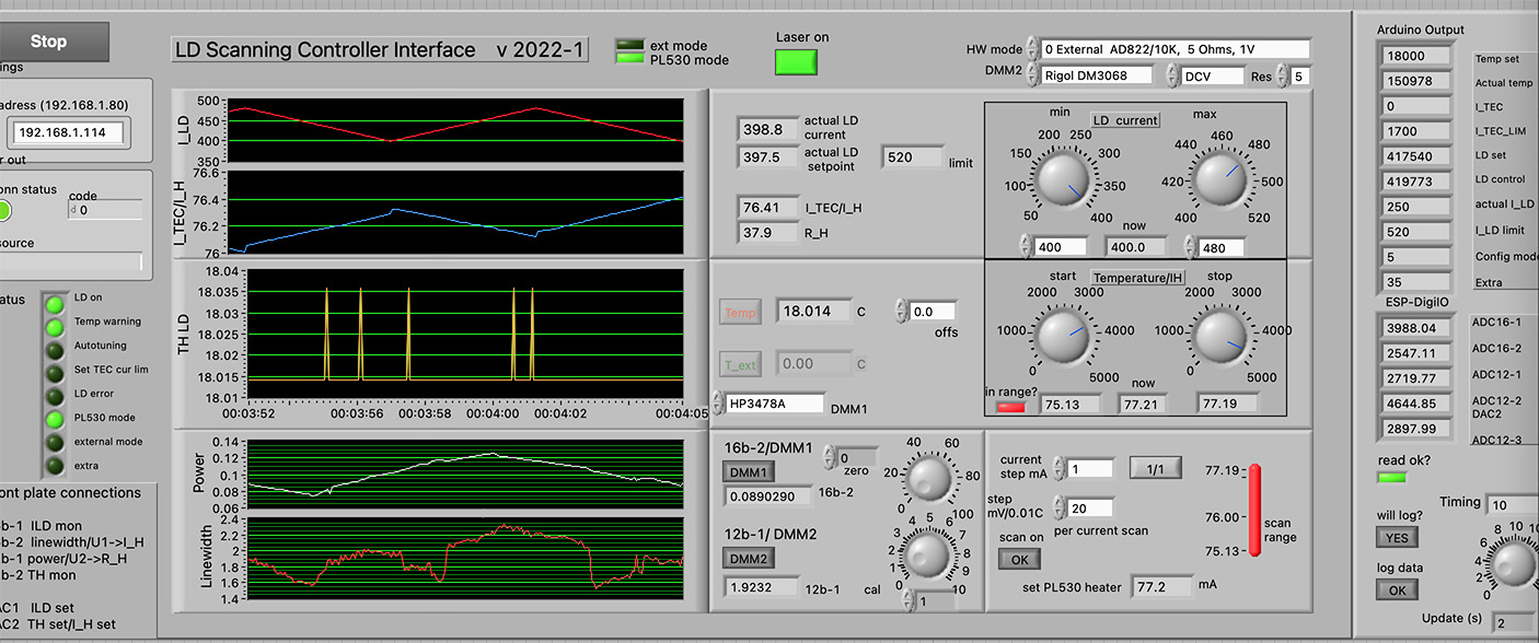
Below is a picture of a LabVIEW interface that shows what happens when the case temperature is changed back and forth:

The spikes in the TEC current show that the PID control loop works perfectly without any overshoots. We also see a modulation of the output power with mode jumps visible in the transition regions. More interesting is the change of heater current I_H which inversely follows the change of the case temperature. This must be so since the heater resistance R_H is forced to stay constant by design, which is also clearly visible here. That is, if the case temperature gets higher, then the heater current has to decrease in order for R_H to stay constant; and vice versa.
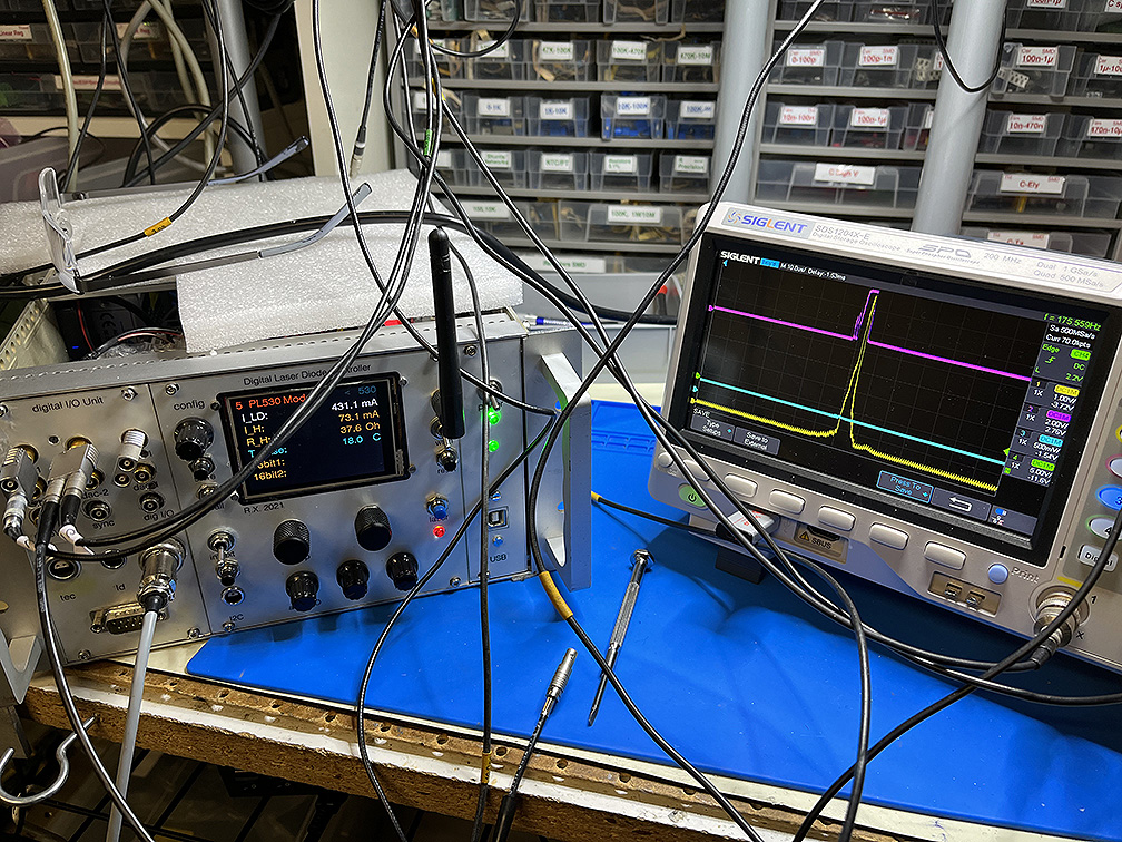
Very similar to my previous investigations of ordinary laser diodes and ECDL lasers, I conducted precise measurements of spectral width, noise in laser output and power, as depending on diode and heater currents. Here we show how the relative line width of a PL530 is determined:
 (click for movie)
On the left there is my new digital controller connected to a PL530 based laser. More details can be found here. The operation can be nicely seen in the movie: the cyan output line goes up in proportion to the line width and is lowest for single mode operation. This is what is color coded in the various scan pictures below.
Automated systematic scanning is controlled via a laptop running LabVIEW connected remotely:
Here are some results:
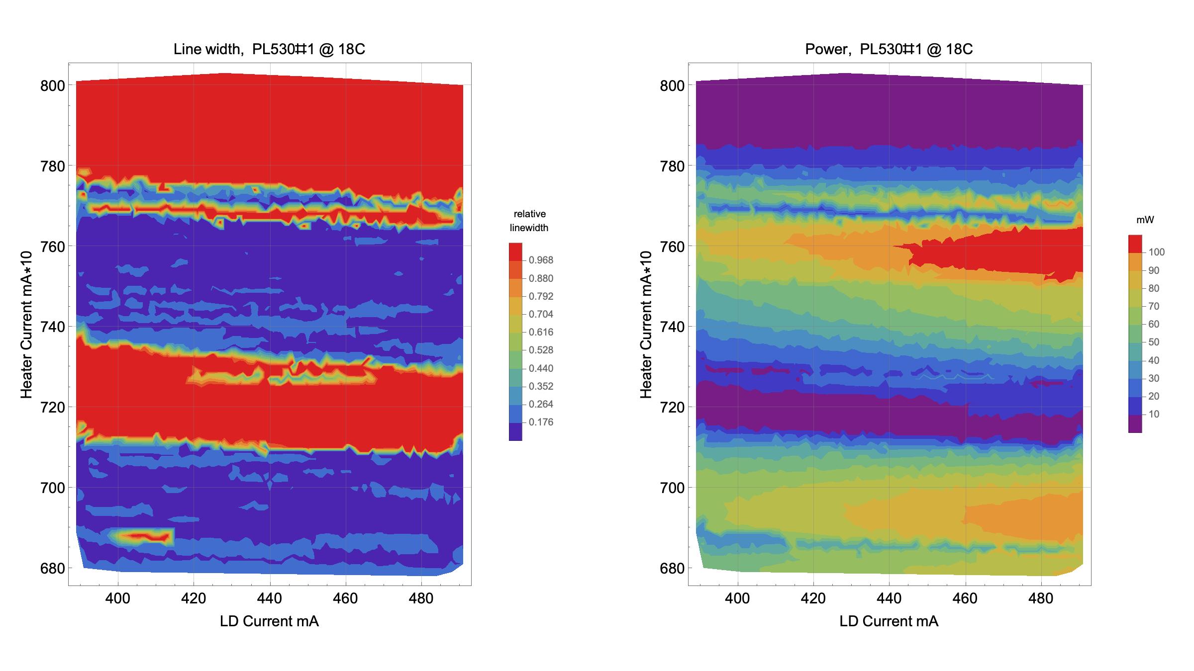
Above to the left: relative line width where purple/dark blue corresponds to single mode. In the middle: noise in laser output, purple is lowest. To the right: Output power.
Here are some plots of line width and power for which the diode current was fixed at I_L=460mA, while case temperature and heater current were scanned:
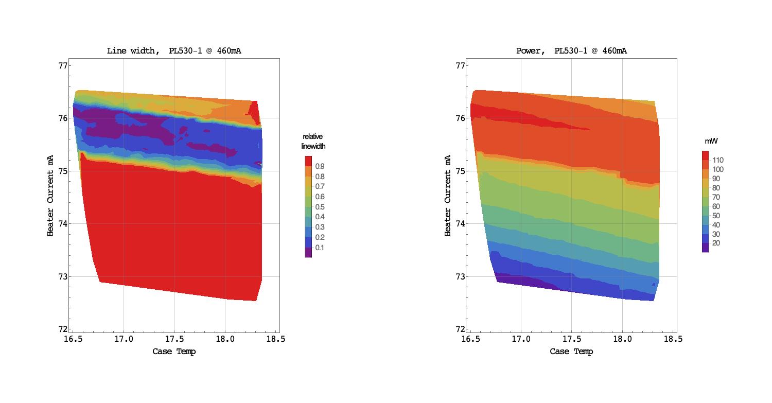
Thus a lower case temperature seems moderately better, but this isn't critical. Fixing it for good around 17-18C is fine.
Take-home message: the spot with maximum power seems generically to be associated with single longitudinal mode operation; this makes life easy as compared to ordinary laser diodes. However, for a counter-example see below.
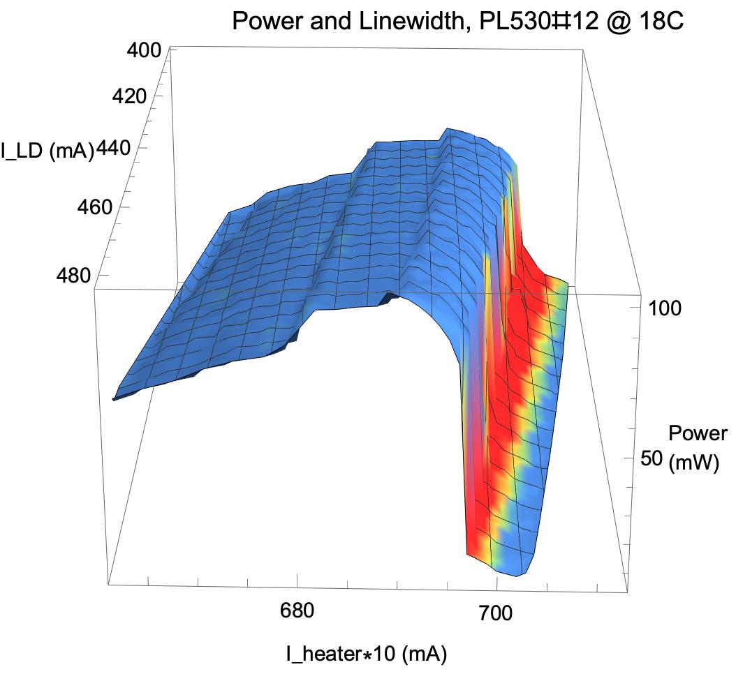
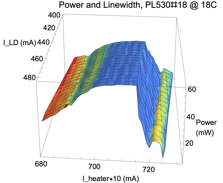
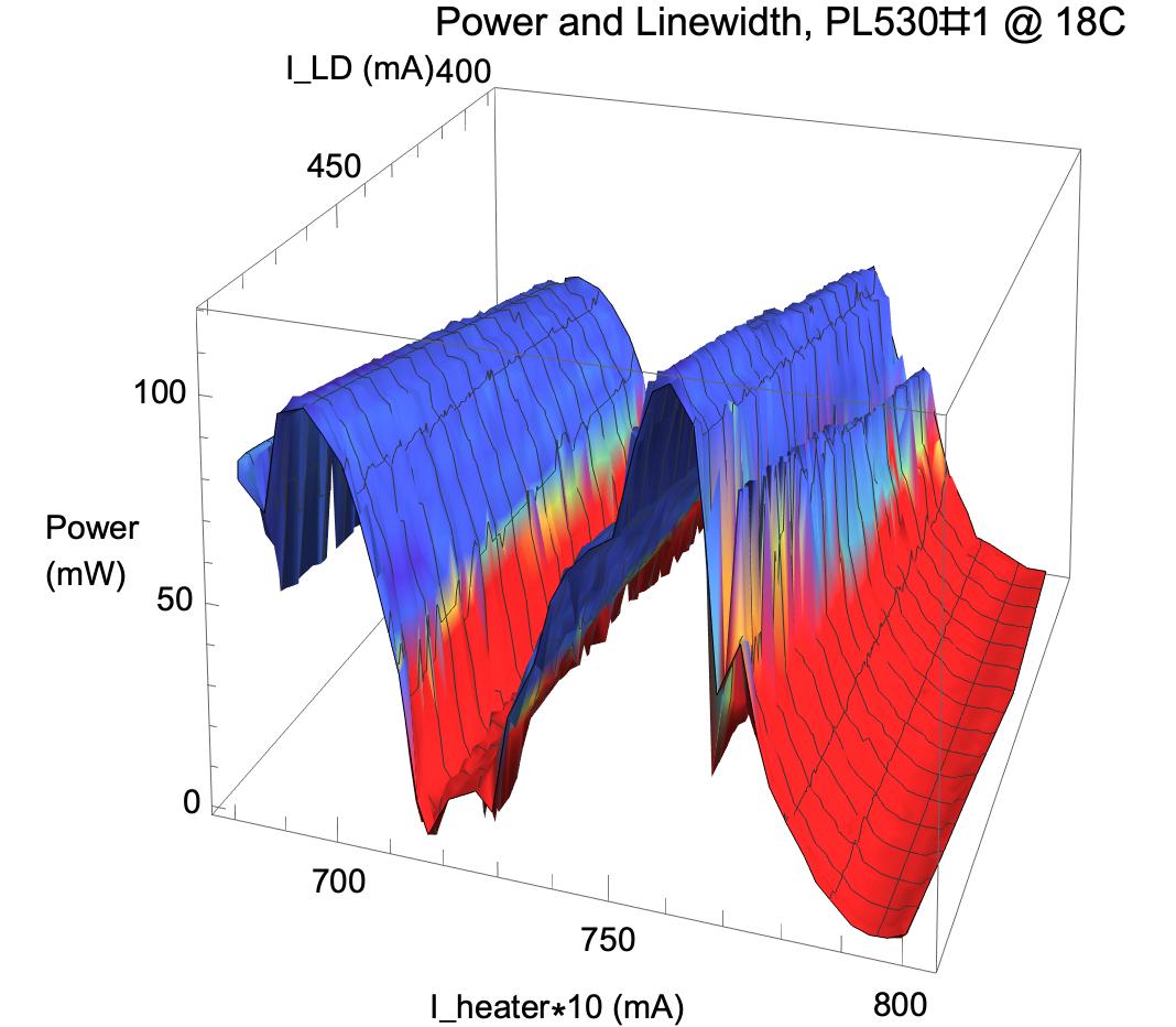
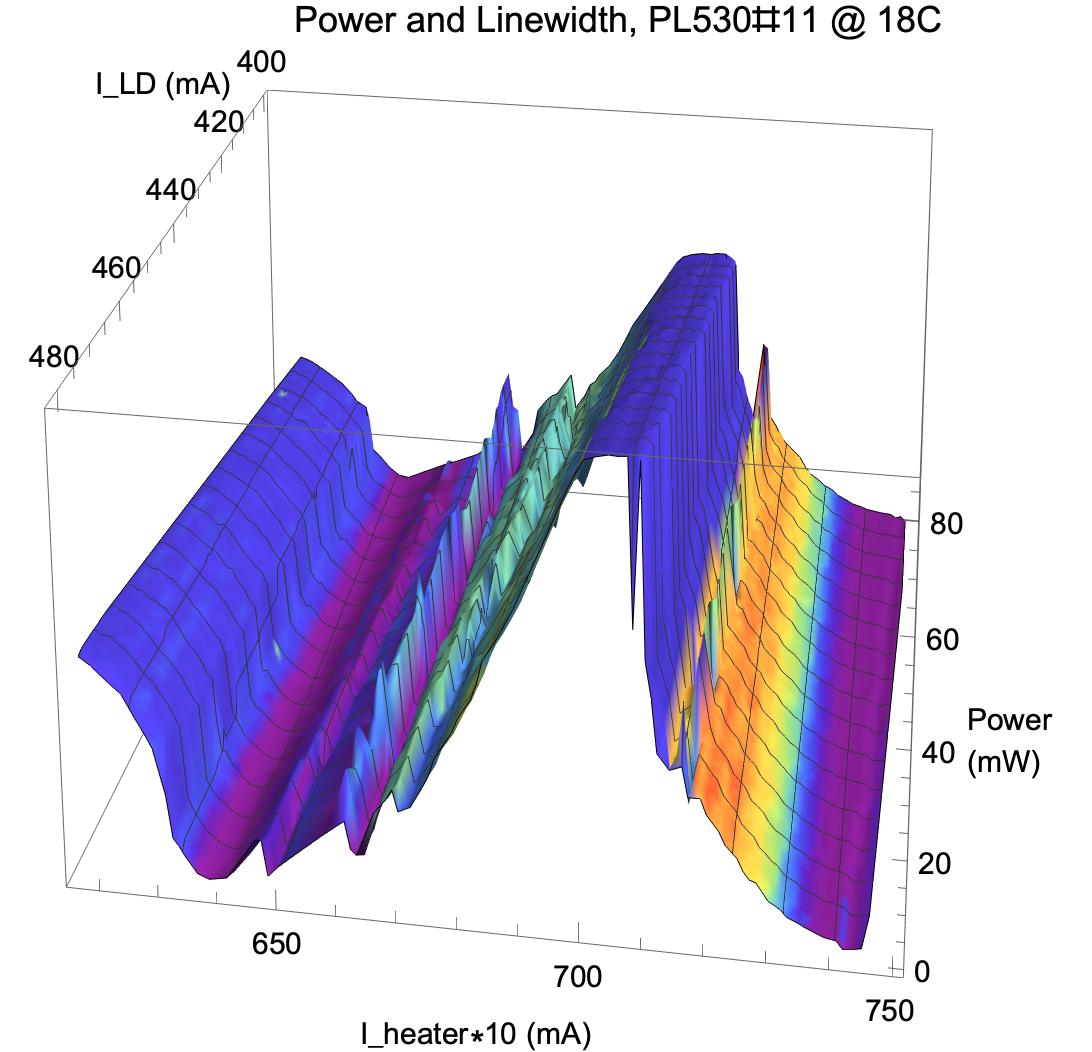
To see this more clearly, it is convenient to package power and line width together into a 3D plot. In the following plots, the height denotes laser power, and the color the line width - blue stands for single longitudinal mode, red multi-mode. Indeed maximal power seems generically to coincide with a clean spectrum, at least for the PL530's that I tested.
All PL530's I tested were from the same batch except #14,#17 (the last two were extracted from a Pico projector with attached collimator). They vary quite a lot, having output power between about 60mW and 130mW, and the sweet spot can be quite narrow or large. The upshot is that one needs to monitor the (relative) output power very closely by some meter, in order to reliably identify the sweet spot if it is narrow; impossible by the naked eye!
These are good and/or benign samples:

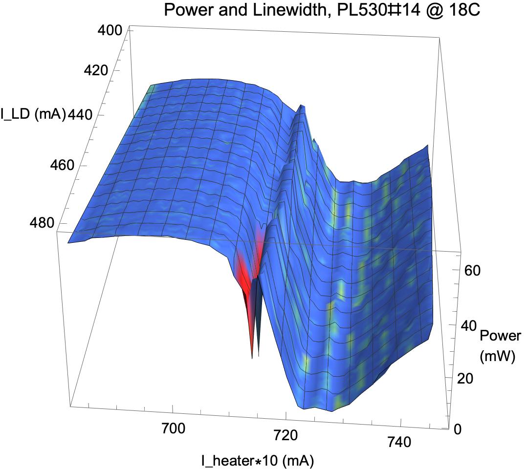
On the other hand, the following three samples have tight sweet spots which require quite some fine tuning (<1mA) of the heater current:
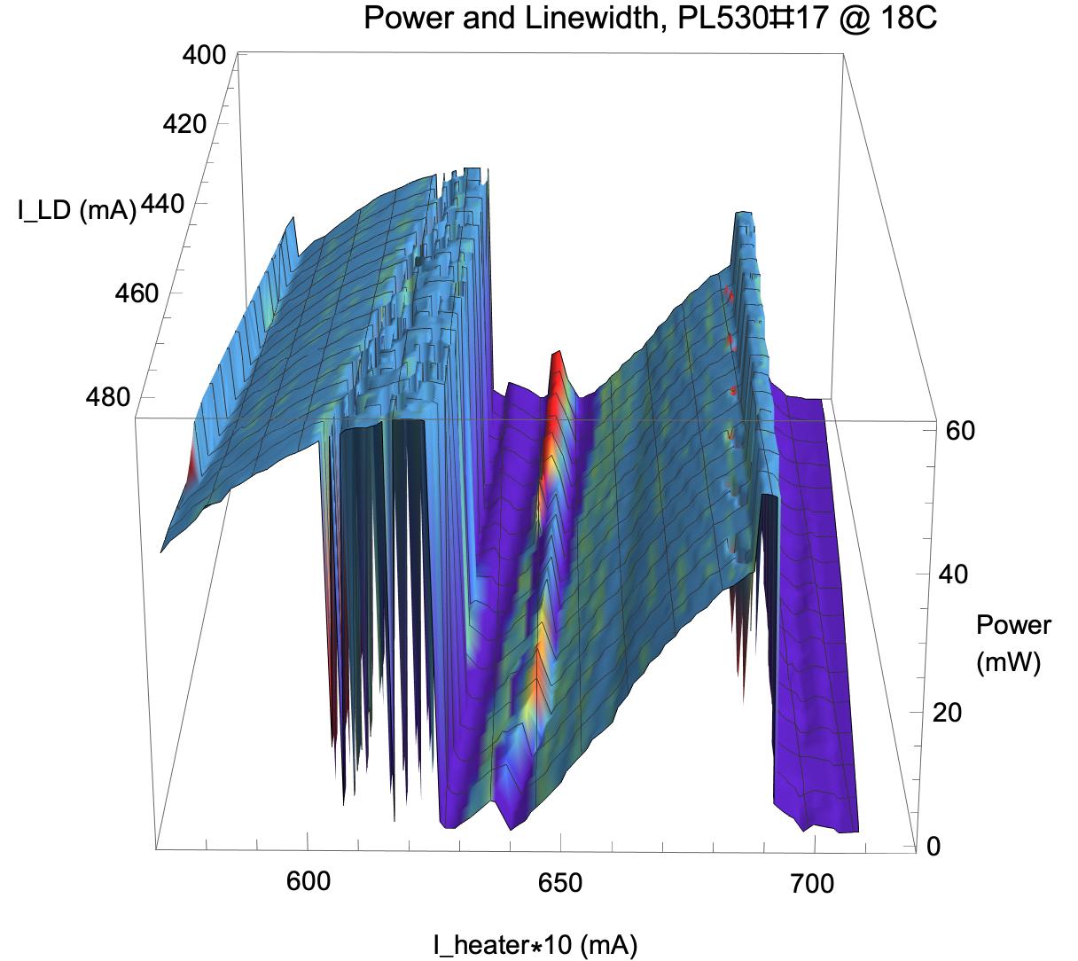
The last one, #17, is especially problematic as the zone with maximal power lies in an unstable region (see the downward spikes). This is quite evident from the 2d plots:
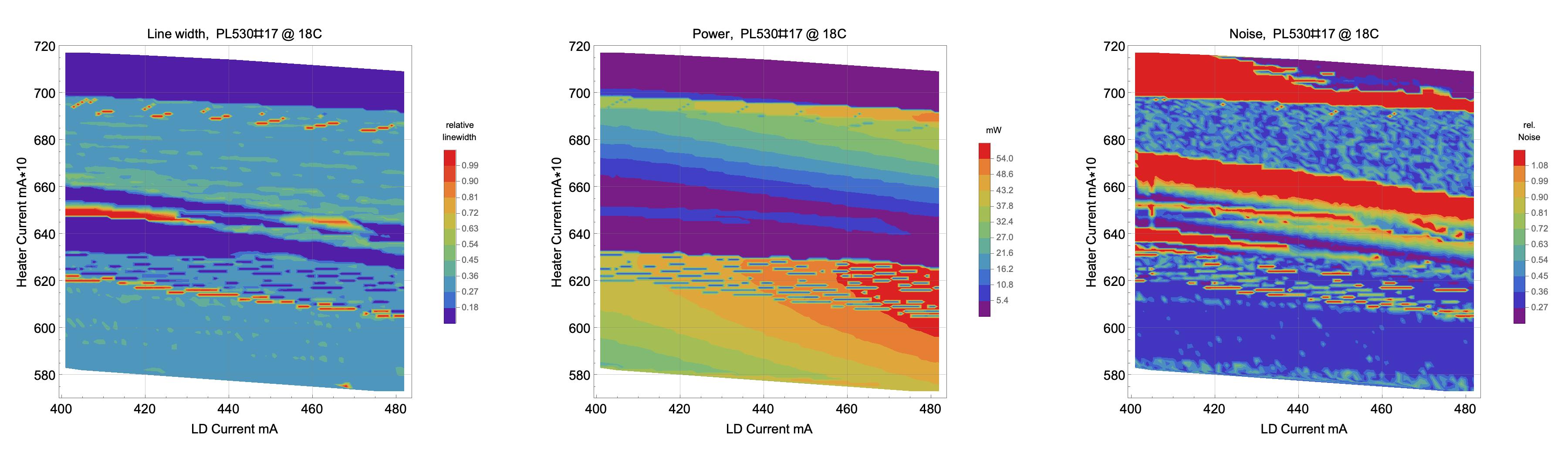
This sample is from an assembled White Light Engine module which has built-in optics (featuring excellent collimation and beam profile). Device #18 is also a sample of a White Light Engine but fares much better:

The stripes in the noise plot indicate mode jumps between different single mode zones and one should better stay away from those.
In summary, the PL530 generically features stable and reliable single mode operation without much effort. Most samples are pretty benign and all what is required is to carefully tune the heater current to maximal laser power. This needs to be very precise and can't be done by the naked eye for less benign samples with a narrow sweet zone. Only exceptionally the zone of maximal power is not the best operating spot.
Version history
Current: Vers. 2.1 Feb 2022
Return to home page