Return to home page
Return to ECDL page
See also:
Converting a 780nm to a 658nm 100mW+ single mode extended cavity laser
Below you find some representative findings for a variety of common diodes; you will see that they behave quite differently and right know I wouldn't know any criterion to decide beforehand whether a laser diode performs well in an ECDL configuration -- single mode operation is by no means automatic! Generically it seems that a diode that is labeled single mode performs better also in an ECDL. But even for the same type of diode there are large fluctuations in the maximally available stable single mode power. It is important that the back-coupling of the grating is optimized to the diode. It depends on the grating itself, but also on the collimator, the adjustment and the resonator length. See here for more background.
Here is a summary for some diodes so far:
1) Rohm RLD65PZB5 80mW/658nm laser diode: unsuitable
2) Sony SLD1239JL-54 100mW/658nm laser diode: unsuitable
3) "long open can" Mitsubushi ML101U29 150mW/660nm diode some specimes did well to 100mW and more
4) Mitsubishi ML101J27 130mW/660nm laser diode stable operation seems generically possible to up 100mW and more; good value
5) Opnext HL6385DG 150mW/642nm laser diode stable operation possible up to 90-100mW, very good
6) Sharp GH04P21A2GE/PHR-803T 100mW/406nm "blu-ray"laser diode: stable to 15mW only
7) Mitsubishi ML101F27 150mW/660nm laser diode: unsuitable
8) Nichia NDB7412 1W/445nm laser diode, borderline tricky, probably not really useful in practice. Due to length put on a separate page.
9) Opnext HL63133DG 170mW/638nm laser diode stable operation to more than 100mW, very good! Highest quality and priced diode so far.
10) Osram PL450 80mW/450nm laser diode ok only for ECDL, 40mW, stability tricky
11) Opnext HL45023TG 80mW/445nm laser diode TBA
12) Opnext HL63603TG 120mW/638nm laser diode ECDL 70mW, very good value
13) Mitsubishi ML520G54 110mW/638nm laser diode ECDL 60mW, very good value
14) Osram PL520 50mW/520nm laser diode ok only for ECDL, 40mW+, good
15 ) Mitsubishi LPC-836 300mW/655nm laser diode: unsuitable
16 ) Ushio HL63643DG 210mW/639nm laser diode: excellent, looks like price-performance leader!
(Mitsubishi ML520G71 300mW/638nm, Opnext HL6388MG 250mW/637nm laser diodes: unsuitable due to multi transverse mode)
Note however that this needs to be qualified - while single mode operation seems often possible beyond 100mW, many diodes become unstable and the single mode zones become very narrow. Such operation regions may not be suitable for practical holography work. As a crude rule, I found so far that generically, ECDLs become unstable beyond roughly 60-100mW, quite independently of diode, grating and operating details. Another crude rule is that best are diodes for red with rated CW power 100-200mW but not more.
The question is thus whether the considerably higher effort to build an ECDL is worthwhile. The answer is that only by a careful matching of diode, collimator, grating, resonator length, adjustment, and operating parameters, higher powers can be reliably obtained (and to find this out, takes most of the effort). Minor modifications, like changing the collimation or the resonator length, can change the picture a lot! The issue is not to just obtain high power single mode operation (which is easy), but also to have a robust and stable operation. One would also like to have a simple means to verify single mode operation; for some thoughts, see here.
Below are the data for the gratings I used, which I measured to a few percent accuracy (I know that not all entries are consistent, but this is the best what I could do). All are 1800 lines/mm gratings blazed for UV, Grating 1 I got from ebay, Grating 2 is gold plated and taken from the commercial 780nm ECDL laser described here. Gratings 3 (model R11-075) and 4 (model 3-462) I ordered from Optispac and Optometrics, respectively, each was around $50 at 12.7x12.7mm^2 size. I had the opportunity to have some of them gold coated, which does not only enhance the reflectivity at red wavelengths but also protects the grating from long term deterioration. I denote the gold coated ones with an extra suffix "g". I didn't find a significant difference when scattering along or against the blaze direction. "refl" and "out" refer to the reflected first order beam back to the diode and the zeroth order output beam, respectively. Moreover "vert" and "horiz" refer to p- and s-type polarization, resp.
| Grating 1 | refl vert | out vert | refl horiz | out horiz |
|---|---|---|---|---|
| 642nm | 5% | 85% | 18% | 67% |
| 658nm | 3.8% | 84% | 17% | 63% |
| 445nm | 12% | 76% | 28% | 30% |
| Grating 2g | refl vert | out vert | refl horiz | out horiz |
|---|---|---|---|---|
| 642nm | 8% | 86% | 31% | 59% |
| 658nm | 6.7% | 87% | 31% | 60% |
| Grating 3 | refl vert | out vert | refl horiz | out horiz |
|---|---|---|---|---|
| 658nm | 7.5% | 81% | ||
| 445nm | 20% | 70% | 28% | 30% |
| Grating 3g | refl vert | out vert | refl horiz | out horiz |
|---|---|---|---|---|
| 642nm | 9% | 84% | 25% | 61% |
| 658nm | 7.8% | 87% | 25% | 61% |
| Grating 4 | refl vert | out vert | refl horiz | out horiz |
|---|---|---|---|---|
| 642nm | 3.6% | 78% | 11% | 50% |
| 658nm | 3.4% | 80% | 12% | 50% |
| 445nm | 7% | 65% | 2.8% | 26% |
| Grating 4g | refl vert | out vert | refl horiz | out horiz |
|---|---|---|---|---|
| 642nm | 8% | 80% | 26% | 46% |
| 658nm | 6.6% | 82% | 24% | 50% |
The entries marked in red I found suitable for high power ECDL operation. Note that the return coupling for blue light is generally quite high, which is not too fortunate, but this is a consequence of the UV blazing and it would be much worse for blazing at visible wavelengths.
Note added (1/2012): Apparently Optispac is not doing business any more. I got a couple of new gratings from China Star Optics Technology, these are holographic gratings (so have somewhat lower diffraction efficiency), blazed at UV. Grating 5 has 1800 l/mm as the gratings before, and Grating 6 has 2400 l/mm, which I got for experimentation with 405nm and 455nm lasers. Here are the data I measured:
| Grating 5 | refl vert | out vert | refl horiz | out horiz |
|---|---|---|---|---|
| 638nm | 8.8% | 77% | ||
| 658nm | 8.3% | 78% | ||
| 450nm | 17.8% | 57% |
| Grating 6 | refl vert | out vert | refl horiz | out horiz |
|---|---|---|---|---|
| 638nm | 6% | 78% | ||
| 658nm | 6% | 80% | ||
| 450nm | 15.5% | 61% |
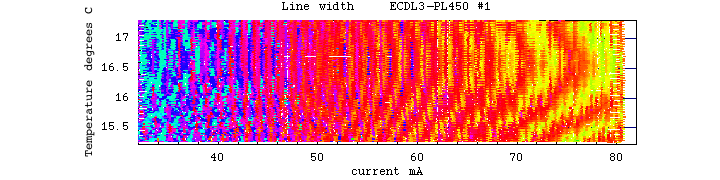
1) Test of the Rohm RLD65PZB5 80mW/658nm diode
This was my first, a bit simple minded attempt:
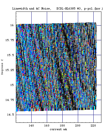
Below the result of some automated scanning over the diode current/temperature plane, done similar as explained here:
On the left: shown is the linewidth of the ECDL laser
as per my optical spectrum analyzer; green/blue
correspond to single longitudinal mode operation.
On the right: AC noise in optical output, which is a measure of mode hops.
The granular structure shows that single - and multimode operating points lie almost dense next to each other, and this means that hitting and maintaining a single-mode point would require quite a fine tuning; in practice this laser would not be usable. It also exemplifies that an ECDL configuration does not automatically guarantee single mode operation.
2)Test of the Sony SLD1239JL-54 100mW/658nm laser diode
Terrible mode chaos, just like for the free-running diode. Perhaps deservedly, the diode died from overheating induced by a faulty thermistor connection.
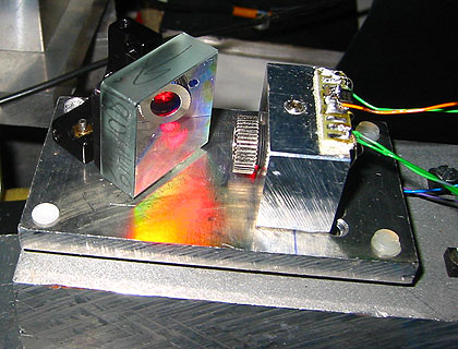
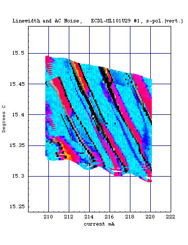
3)Test of the Mitsubishi ML101U29 "long open can" 150mW/660nm diode
I achieved 100mW at approx 220mA without problem. Almost no sign of multimode operation at currents < 170mA. I used Grating1 and vertical polarization. Here a scan over the current/temperature plane, with noise superimposed as black:
Thus, we see differences as compared to a blank, non-grating stabilized diode laser. The general pattern is much more uniform than for a non-EDCL diode laser, in this case it is single mode operation up to approx 170mA. The slight variation of color is due to the change of output power (which simulates a slight change of line width). Mode hops, signified by "black" noise, occur on regular bands. Thus changing the current by just very few mA typically induces a mode jump, and the same applies to changing the temperature by a few hundredths of a degree.
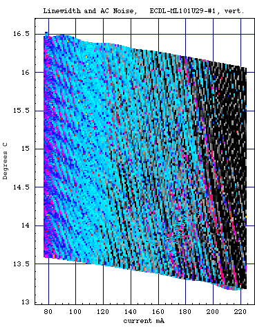
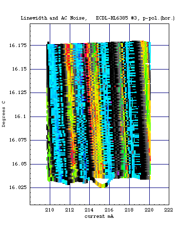
Here are zooms at around the same temperature, for lower and higher powers:
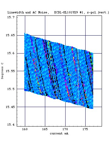
We clearly see that at lower powers, there is almost everywhere single mode operation, and mode hops between different modes occur at regular bands. However at higher powers, seen on the right (around 100mW), there are multimode zones interspersed with single mode zones, and adjusting to, and staying in, a single mode zone becomes more of a challenge. So staying below 170-180mA gives less power, but apart from occasional mode hops there wouldn't be much to fear.
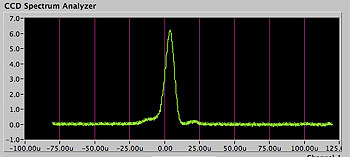
Note that there are in principle two or three relevant length scales (and thus possible longitudinal mode spacings) in the laser: first, the optical length of the diode cavity (which gives a mode spacing of say, 100Ghz), then the distance to the diode output window (which is irrelevant for an open can diode), and then the distance between the diode and the grating. While the CCD spectrum analyzer can well detect the modes of the diode itself, its resolution may not be enough to distinguish modes from the external cavity (in particular if the cavity is large and thus the mode spacing small).
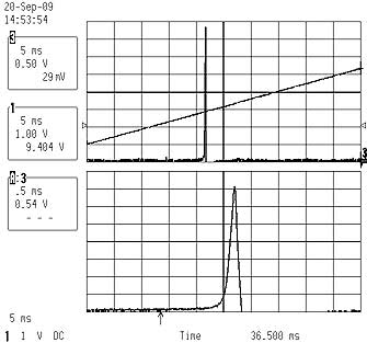
Thus to be sure I checked the spectrum also with my scanning interferometer which has much higher resolution. The result shows a line width of less then 5Mhz:
 (T=17C, P=90mW)
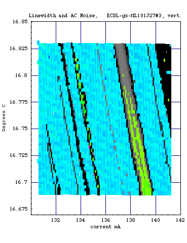
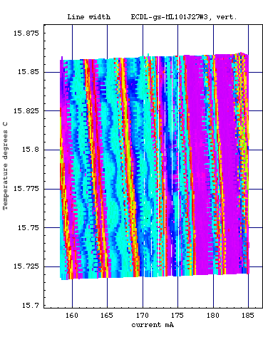
4)Test of the Mitsubishi ML101J27 130mW/660nm laser diode
This diode behaves very well in free-running but even more so in ECDL configuration. Without any optimizations, for vertical p-polarization I achieved 110mW single mode at 160mA current right out the box, at around 19C. However, the single mode zones were quite narrow, like 1mA.
Here a representative landscape scan; as always, colors encode linewidth (cyan corresponds to single mode), and superimposed gray/black noise indicates mode hops:
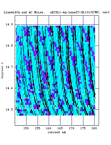
We see that there is predominantly single mode almost everywhere, even up to 180mA which yields about 100mW. However within single mode zones there are mode hops between different single modes, which is indicated by the black noise lines. I also made a comparison how things look for different gratings and collimators, for the same diode and operating region. The results are interesting:
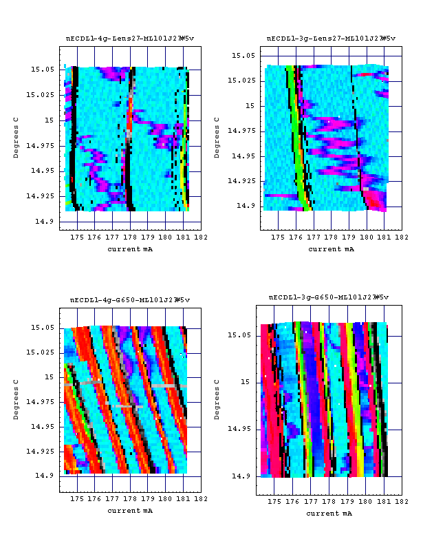
On the upper row, the collimator was the Lens-27 from Roithner. The label "4g" or "3g" refers to the gratings described above. On the lower row, the G-650-1 collimator was used; it has just a few percent less efficiency, but makes a drastic change with regard to the zones of single mode operation. The approx power at 180mA was (clockwise from upper left): 100mW, 104mW, 96mW, 100mW, which is consistent with the fact that Lens-27 and grating 3g are a few percent more efficient than G-650-1 and grating 4g.
We conclude that optimal results can be achieved when all factors (diode, operating point, collimator,grating, adjustment) happen to conspire together in a fortunate way; minor modifications can completely change the picture.
When repeating the test for p-polarization (horizontal), the power was considerably lower, namely 68mW at 160mA. The diode died at 180mA, which is well below the maximal current rating of 200mA. However what counts is the power density at the diode facet and this must have been too large due to the larger feedback from the grating.
I have put that diode also in the converted, commercial 780nm ECDL described here. It uses Grating 2 which has somewhat higher reflectivity, and an unspecified aspheric lens. Here the result:
We see that there is generic single mode operation only at relatively low power. Below are higher-resolution zoom-ins at around the same temperature but different currents, the right shows the region near 100mW:
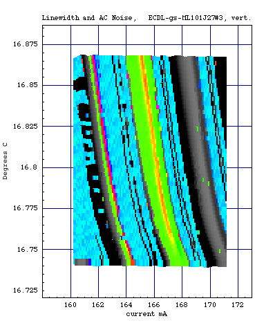
We see that at higher power the single mode zones become more narrow, which is as expected because of the higher gain so that more modes tend to oscillate. The separation of mode hoping zones is in the order of 1mA which requires a very precise current control.
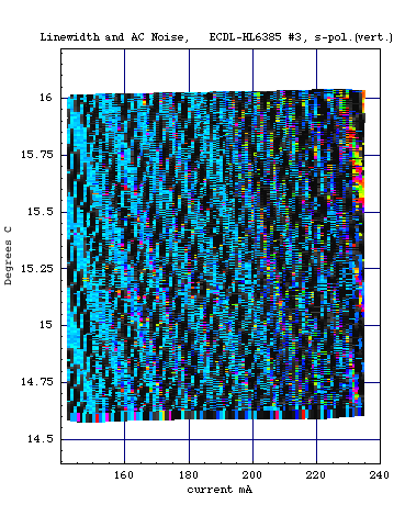
5)Test of the Opnext HL6385DG 150mW/642nm laser diode
Lots of people have expressed a desire of a 100mW or so single mode laser at 640nm. I found that free-running diodes can be reasonably stabilized only up to around 70mW, so why not trying an ECDL setup. So I crossed my fingers and put my last HL6385 diode in the simple ECDL setup described above. I was careful and started with vertical polarization which gives a feedback of like 3.8%. I found it to produce 105mW single mode at 239mA at around 17C without effort, but remembering what happened to my best Mitsubishi diode I didn't dare to turn it up higher, so I don't know what the limit is; I just content myself with 100mW for the time being.
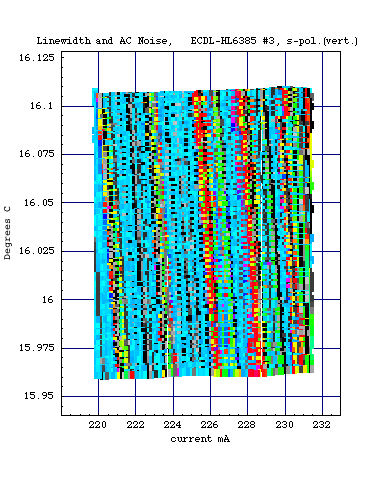
Below are two scan plots, the left shows an overall picture and the right one is a higher-resolution zoom at around 100mW. As always, colors encode line width (cyan corresponds to single mode), and superimposed gray/black denotes noise which signals mode hops:
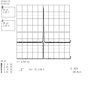
Here a check with the scanning interferometer at 230mA:
Top scan is about 200Mhz/Div, lower scan is ten-fold zoom at approx 20Mhz/Div. The displayed line width is limited by the resolution of the SFPI and at most like 10Mhz. This corresponds to at least some 30m coherence length. However this is so only in optimal circumstances, minute changes of the operating point can create complete mode chaos.
Getting a bit more adventurous, I switched the polarization to horizontal to check out stronger feedback (approx 18%). Surprisingly, not only the power (75mW at 225mA) but also the spectrum got worse, it is like for the Rohm diode above:
Note the fragmented structure of the bands, it reflects hysteresis effects because the current scans in alternating directions. In other words, a mode can jump at slightly different values depending whether you had increased or decreased the current.
So all-in-all, it seems that the stability gets worse with larger reflectivity of the grating. Thus, due to the larger feedback, the laser has an increased tendency to run multimode -beforehand, I had thought it would be the other way around!
6) Test of the Sharp GH04P21A2GE/PHR-803T 100mW/406nm "blu-ray" laser diode
Since the longitudinal mode spectrum of the free running blu ray diode is intolerable, an obvious question is of whether an ECDL setup is of any help. A single mode laser at 406nm would be particularly interesting for DCG holographic emulsions since the sensitivity of those is dramatically better as compared to green DPSS lasers, say.
I placed the diode in an Aixiz 12mm mount tube (itself located in an alu brick), of which I had removed part of the 9x0.5mm thread in order to fit a broadband, 400-600nm coated Geltech C330TM-A lens.The grating was the same as above, which is UV blazed at 1800 lines/mm. The angle needed to be changed from 54 to 69 degrees, see the diagram above. Also I used vertical polarization.
I achieved 14mW at 50mA, 38mW at 85mA and 51mW at 100mA, which is in the order of 50% as compared to the bare diode. On the CCD spectrum analayzer the mode spectrum looks as follows:
 (T=15C, I=50mA,P=14mW)
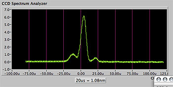 (T=15C, I=60mA,P=20mW)
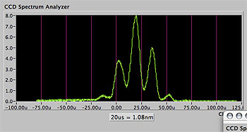 (T=15C, I=100mA,P=51mW)
Thus, while this is much better as compared to the free running setup, the diode is not really usable for holography beyond 15-20mW or so because it ceases to run single mode; this is consistent with what I saw for the the 405+/-nm laser diode specs at Toptica. I didn't yet perform a systematic scan over diode current and temperature, and thus cannot exclude domains which are better behaved. Moreover, perhaps also fine tuning the adjustment, in particular of the collimator lens, would improve the mode structure. I may try if I got around doing it.
Note also that the apparent line width is somewhat larger as compared to the one shown in the plots for the free running setup. As said above, the CCD can distinguish only the modes coming from the diode cavity itself, and these are the ones shown here. In principle, the laser could still run with several modes of the extended cavity, and the apparent increase in line width may just indicates this. On the other hand it may also be due to the fact that the diffraction order for 406nm is different and thus the resolution of the CCD spectrometer. In order to check this and find a possible fine structure with the scanning interferometer, I'd need however suitable high reflective and curved dielectric mirrors for 406nm for the latter, and I have no idea where to get those from.
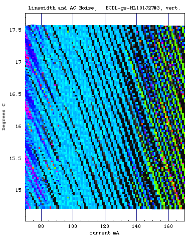
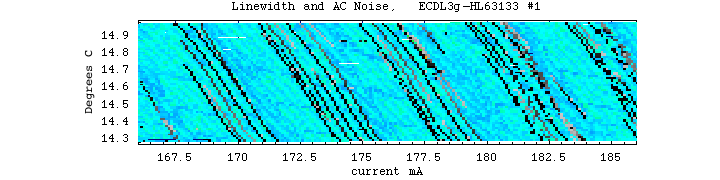
7)Test of the Mitsubishi ML101F27 150mW/660nm laser diode
This open can diode is similar to the ML101U29 diode: free running totally useless for holography, but decent diode for ECDL setups, I achieved 80mW single mode at 172mA without problem (grating #2, diode vertical polarized). The high resolution plot looks like this (the diode was wrongly labeled on the plot, it should read ML101F27 #1):
8) Test of the Nichia NDB7412 1W/445nm laser diode: see separate page
9) Test of the Opnext/Ushio HL63133DG 170mW/638nm laser diode
This is a narrow-stripe single transverse mode diode, which is similar to but somewhat better then the proven HL6385 (and definitely more expensive). It runs moderately well in free-running mode, but runs great in ECDL mode; I used grating 3g and a aspheric collimator. Here a current/temperature plot with superimposed noise in gray:
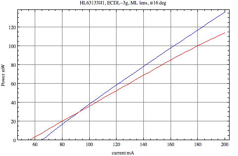
We see that apart from the mode hopping zones, the diode runs single longitudinal mode practically everywhere! At 180mA an output of 100mW was achieved, and certainly more can be done but I didn't want to risk the expensive diode. As is looks so far, this is the best diode overall! Here a picture of nice clean, and stable single mode operation at 100mW:
Finally, here a plot of output power (blue= free running diode, red=ECDL with grating 3g):
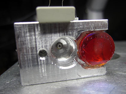
10) Test of the Osram PL450/PL450B 80mW/100mW/450nm laser diode (3.8mm case)
In free-running mode this diode is completely useless for SLM operation, and at first it seems to be not too great in ECDL mode either, but there is some hope that with careful optimization a decent SLM laser can be made.
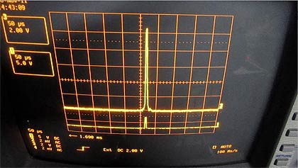
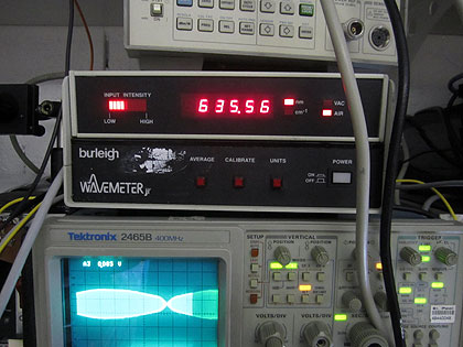
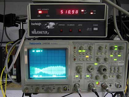
Only in ECDL mode the spectrum is narrow enough such as to give a reasonable readout of the Burleigh WA2000 Wavemeter:
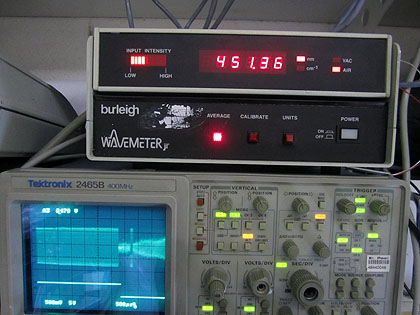
Bottom scope shows the single mode signal of the scanning Michelson interferometer inside the WA2000.
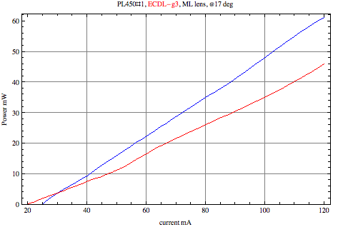
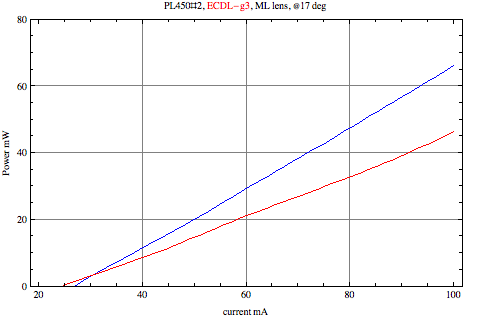
Here a comparison of output power at 448nm in free-running (blue) and ECDL mode (red):
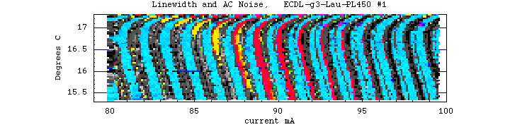
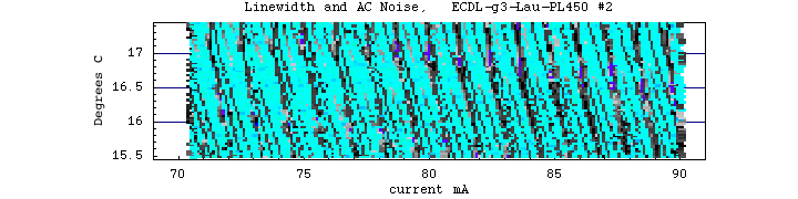
Here a plot for my first configuration using an Axiz 445nm lens and grating Nr.3, and we see that SLM (cyan) arises only at very low powers:
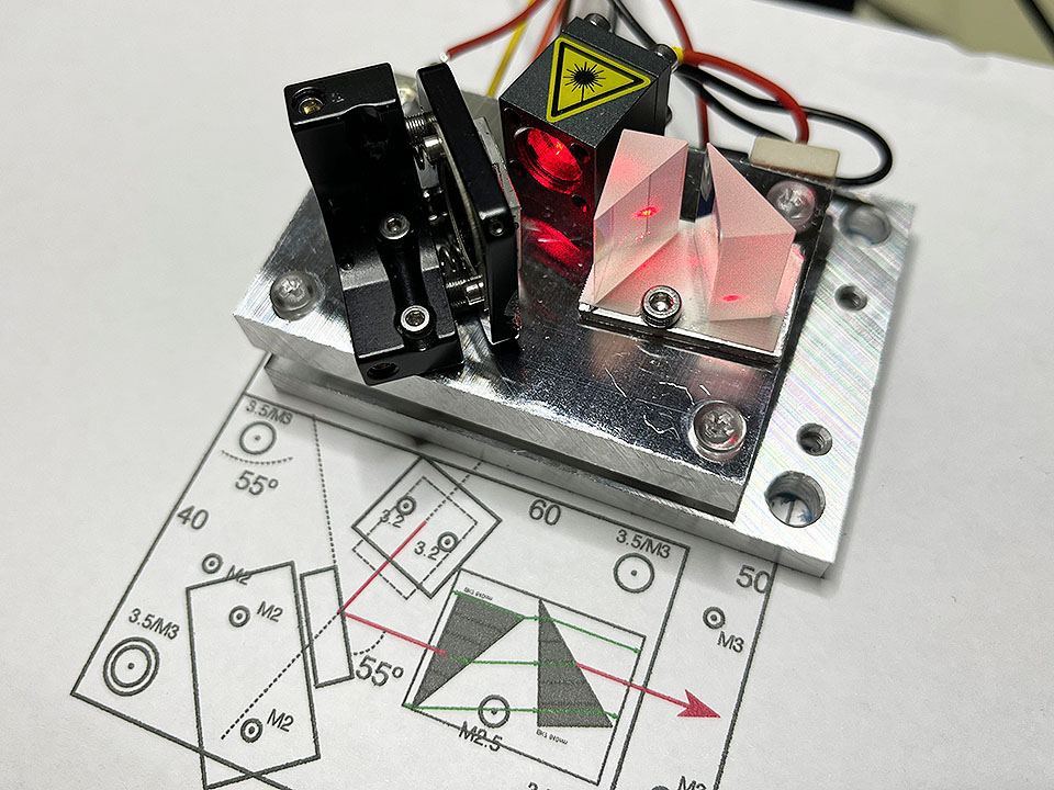
However, this was for the first setup, and next I improved the back coupling of the grating by using a high quality collimator lens (from Marco Lauschmann). Also, a short resonator length was important. To achieve this, I placed the grating close to the diode mount, and in order for the beam to pass the mount, I attached a 45 degree dielectric mirror on it; see the pics:
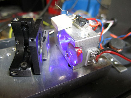
With some careful tinkering with adjustments, more than 40mW in SLM operation could be achieved:
Here, as always, superimposed gray shows noise in the light output, and we see that in zones where there is no noise there is clean single mode operation. I found the alignment to be very critical, the stability depends very much also on the collimator adjustment, and it seems that this is sensitive to like 1/100 turn! This can probably pushed up even a bit more, but I didn't try more than 115mA in order not to risk the diode.
Here a brief movie (2MB) showing single mode operation from the CCD spectrum analyzer at around 40mW (mode jumps indicated by popping sounds):
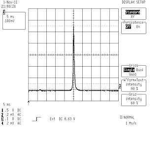
The scanning interferometer shows a linewidth of less than approx. 10Mhz, so the coherence length should be at least several tens of meters:
Due to a foolish mistake, I eventually killed this diode. The second one proved to be similar, except that had a substantially higher efficiency:
Again, stable SLM operation beyond 40mW could be achieved after a very careful adjustment of the collimator:
11)Test of the Opnext/Ushio HL45023TG 80mW/445nm laser diode
TBA
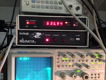
12) Test of the Opnext/Ushio HL63603TG 120mW/638nm laser diode (3.8mm case)
I tested one of those and it ran very stable in ECDL operation. This diode is pretty cheap on ebay and also have a wavelength close to HeNe, a slight disadvantage is the 3.8mm housing. Here a graph of output power in free running and in ECDL mode with grating G3, both with Lauschmann collimator for 650nm (focus point at 2m):
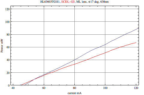
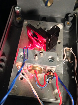
This diode proved very stable in excess of 60mW! Probably part of the reason is a very short resonator, of about 1cm. This was possible by a construction using a 12mm brass tube mount for 3.8mm diodes sold on Laserfreak.de. It was embedded in one of my standard aluminum mounts, and the overall mechanical stability could probably be improved by a dedicated design, but for the sake of demonstration this would do:

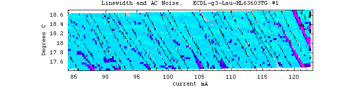
The mode scan shows very good stability until approx 120mA:
Here a brief movie (1.7MB) showing single mode operation from the CCD spectrum analyzer at around 70mW (mode jumps indicated by popping sounds):
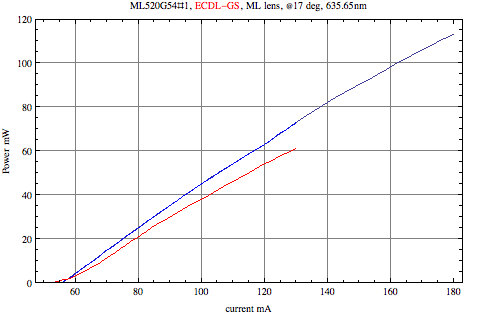
13) Test of the Mitsubishi ML520G54/110mW 638nm laser diode
This diode has been a good surprise: I tested 3 samples and all ran very stable SLM in ECDL operation. They are pretty cheap on ebay and also have a wavelength close to HeNe, so they are a very good value. Here a graph of output power in free running and in ECDL mode with grating G3, both with Lauschmann collimator for 450nm (focus at 2m):
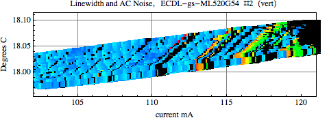
The mode scan looks pretty good:
I used this diode in a laser setup based on the commercial laser described here.
Here a brief movie (2.3MB) showing single mode operation from the CCD spectrum analyzer at around 60mW (mode jumps indicated by popping sounds):
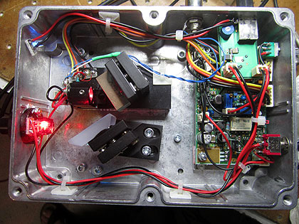
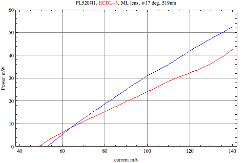
14) Test of the Osram PL520 50mW/520nm laser diode (3.8mm case)
This is the first relatively cheap green diode and obviously I was eager to test it. Free running it is hopelessly running multimode, but in ECDL mode it runs very well and stable to 40mW and beyond. Here a graph of output power in free running and in ECDL mode with grating G3, both with Lauschmann collimator for 450nm (focus at 2m):
The first run was only moderately good:
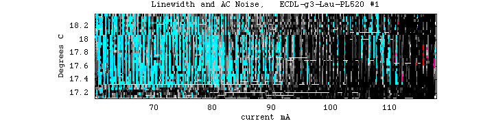
It turned out that the diode runs very stable when using a 2400l/mm grating G6:

The major benefit is that due to the larger deflection angle, the resonator length can be minimized to about 1.5cm.That was possible by using the 3.8mm diode mount made by Guido (a mechanical masterpiece, many thanks!), which has a beveled corner so that the grating can be very close to the diode while the beam is not obstructed:

Here a movie (2.7MB) showing single mode operation from the CCD spectrum analyzer at around 40mW (mode jumps indicated by popping sounds):
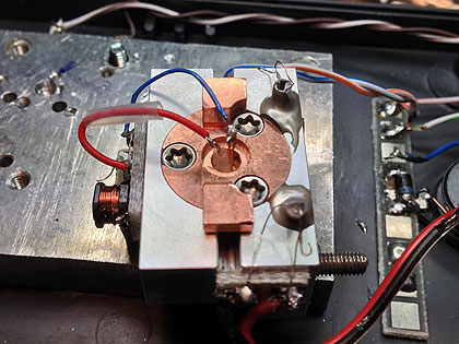
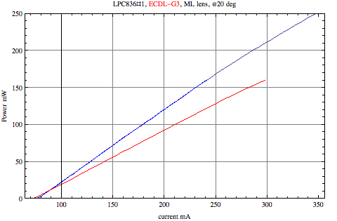
15) Test of the Mitsubishi LPC-836 300mW/655nm laser diode
This diode runs strongly multimode even in ECDL setup, and despite some tinkering, I didn't get it any better than that:
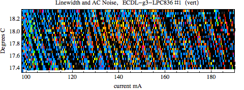
Probably the huge gain that these diode have makes the single longitudinal mode practically impossible, even at lowest currents. A pity, as these diodes have excellent beam data.
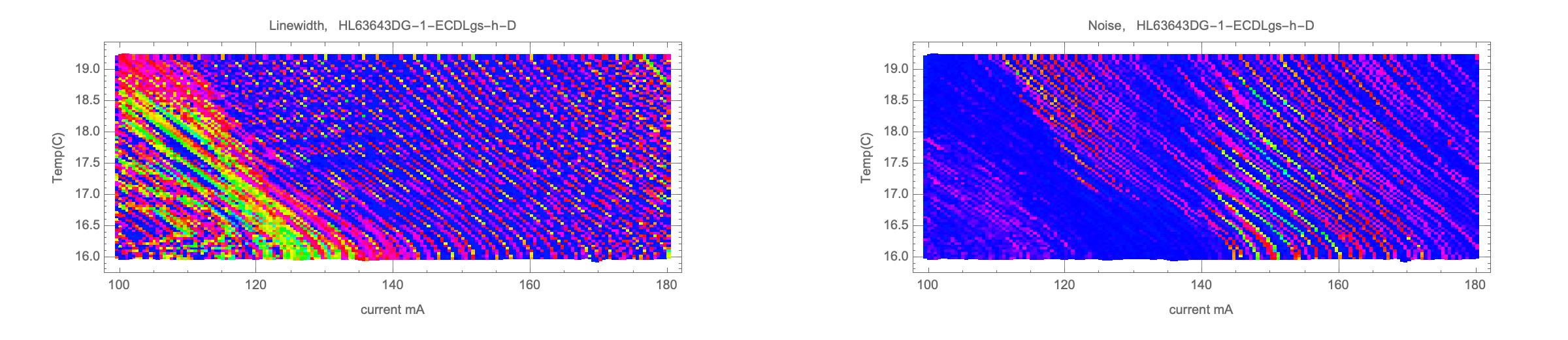
16) Test of the Ushio HL63643DG 210mW/639nm laser diode
This recent (2022) inexpensive diode turned out, at least the samples I checked, to be en par with the much more expensive HL63133D, and appears for now as the price-performance leader for ECDL! However this statement still needs to be strengthened by testing further samples and setups.
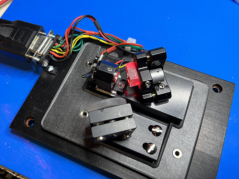
For the first series of tests I used the robust "Thermo" ECDL I got from G.S., described in more detail here. This is how it looks when the cover is removed:
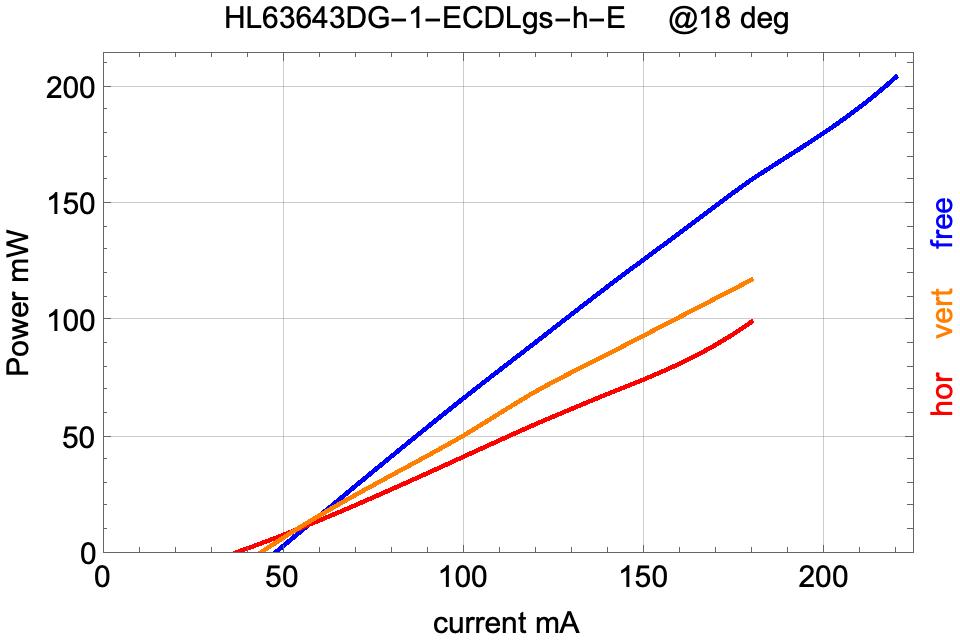
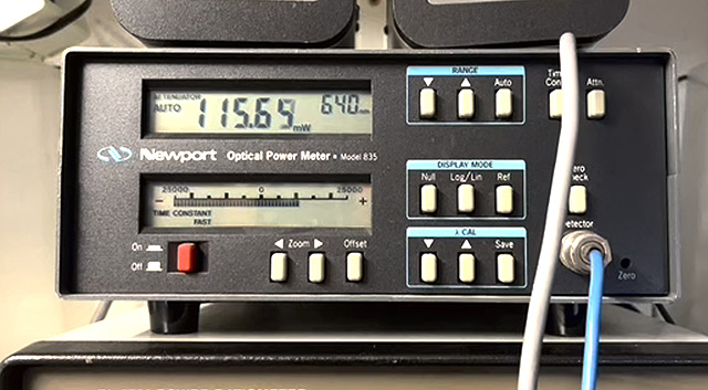
Here is the power plot for the free-running diode versus ECDL with horizontal and vertical polarizations:
As explained before, the mode behavior does not only depend on the diode and its operating conditions, but also on the adjustment of the grating and collimator, and the polarization. This is why I conducted a variety of tests.
First with horizontal polarization, which yields a stronger backcoupling of the diode than the vertical one. This turned out to lead to instabilities, so I tried to ameliorate this by changing the collimation, and/or detuning of the grating. Here some results, which are a bit crude as higher resolution scans take a lot of time.
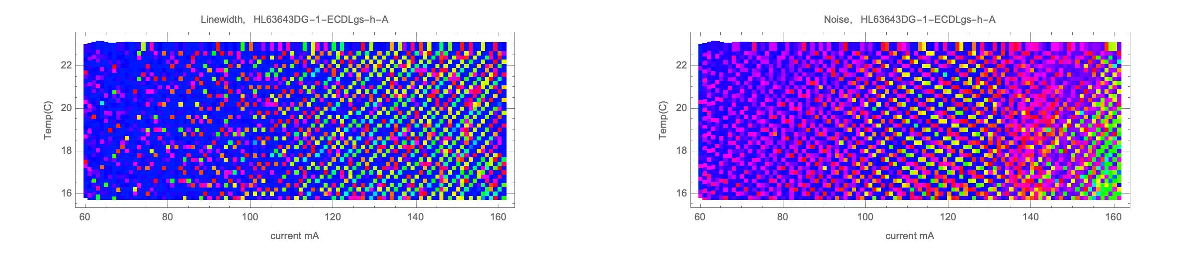
Version A: focus 2m, horizontal pol, threshold at 18C: 36.1mA. Strongest backcoupling with lowest threshold current, but multiple modes prevail:
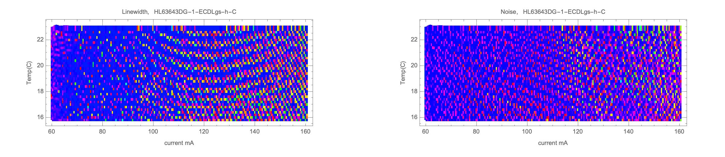
Version C: focus 50cm, horizontal pol, threshold at 18C: 42.2mA. Slightly better:
Version D: focus 50cm, horizontal pol, large detuning of grating, threshold at 18C: 45mA. This is interesting as the feedback was so small that at low currents the diode run multimode like without grating, as the tuned wavelength was too far off. At around 120mA the gain increased enough so that the grating could take control. The wavelength made a considerable jump and the spectrum turned to be more ECDL-like:
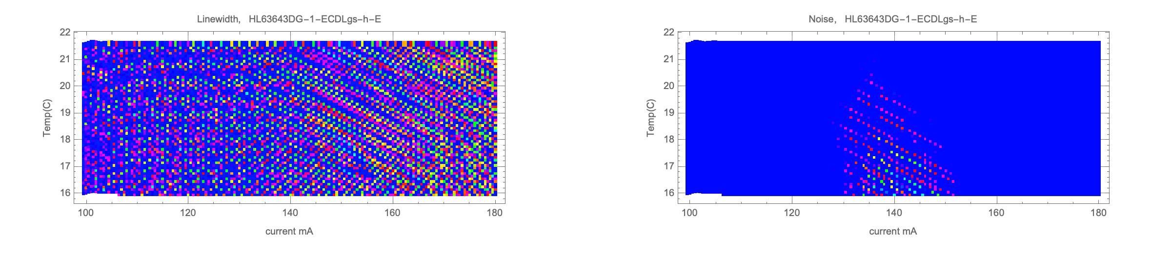
Version E: focus 4m, horizontal pol, slight detuning of grating, threshold at 18C: 47mA. This configuration is kind of in-between the previous (the noise detection was not properly set up):
Version F: finally I turned to vertical polarization, which gives less feedback and more power. Threshold was at 44mA. The story improved dramatically: at the upper end 120mW was reached, and still no sign of major instability:

I didn't go higher up in order not to risk the diode, but instead made a further scan with 100uA resolution:
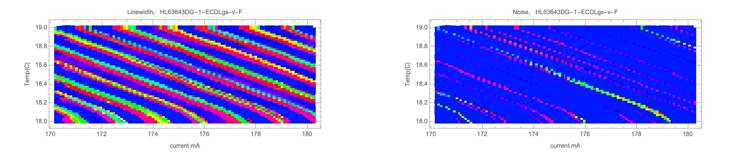
This is as almost good as it can get: clean single mode in bands of about 1mA width, separated by transition regions. After sufficient time for stabilizing, it wasn't any problem to maintain single mode operation for an hour or so. As proof here the obligatory movie:
We see that sometimes multimode operation appears in the transition regions -- typically this gets worse with higher powers.
Here a test of a second sample of the HL63643DG, with grating 3g (vertically polarized, about 9% back reflection), Lauschmann aspheric collimator with focus 1m, and short resonator (about 2cm).
This displays a similar banded pattern with SLM operation well beyond 100mW:
So again, you see that at low power single mode zones dominate, while they get more and more interspersed with multi-mode zones with increasing powers. Thus one has to choose a trade-off between power and single mode robustness.
Further extensive test with this diode in a commercial New Focus Vortex ECDL are described here.
Stay tuned for further results.
Return to home page
Vers 4.6/4-2022