Return to home page
General Remarks
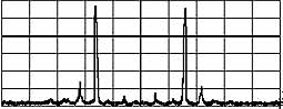
It' interesting and instructive to check the longitudinal mode structure and coherence length of various lasers, especially for holography use (one of my long term projects is a high power DPSS ring laser, and it will be important to know the mode structure). So why not try to build a scanning interferometer. The idea is simple: make an interferometer with two parallel mirrors, slightly transparent, and feed the laser from one side and put a photodiode at the other. One of the mirrors is mounted on a piezo ceramic, and applying a triangle voltage moves it periodically by a wavelength or so. Then, ideally, one can display the spectrum on an oscilloscope, where x-axis = ramp voltage, y-axis=photodiode current.
Alas, things are in practice by far not that simple - I didn't appreciate before how rich this story is! For an excellent and detailed discussion see, as usual, Sam's LaserFAQ; there is no need to repeat it here. Let's just mention that in order to have a good resolution ("finesse"), one needs dielectric mirrors, with 99% or so reflectivity. In order to avoid spurious modes, one needs a mode degenerate resonator, like a confocal configuration (mirror distance=radius of curvature "ROC"). For having a useful scan width (free spectral range, "FSR"), the radius of curvature of the mirrors should be as small as possible, say a few cm. Such highly curved dielectric mirrors are very hard to get as surplus, since they are not often used. This makes it difficult for a hobbyist to build an SFPI in the first place.
But, as so often, recently eBay came to the rescue, and there were dozens of highly curved dielectric mirrors available at minimal cost, originally made by Spectra Physics for dye lasers. I had to get a variety of those, of course, and play with them. I didn't appreciate beforehand how much fun and insights this would produce! After a couple of months everything worked more or less as expected, and the results are shown here..
Note also that a scanning FP interferometer, while resolving a few Mhz of line width, spans in general only a few 100Mhz and so is most suitable for lasers with mode spacing of this size, ie, for lasers with long cavitites (at least a few tens of centimeters). For shorter cavities, and thus larger mode spacing, the display becomes ambiguous as the modes "wrap around" the display; while one can see whether there are extra modes present or not, it is hard to judge their spacing. Thus for shorter cavities, such as for DPSS laser pointers or laser diodes, a grating based optical spectrum analyzer will be more useful for displaying the longitudinal mode spectrum.
Comments on the construction (old)
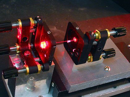
Left pic: Lasing without a laser medium ? It almost looks
like that !
Shown is a first test setup on a linear stage, with beam from a 655nm/80mW laser diode.
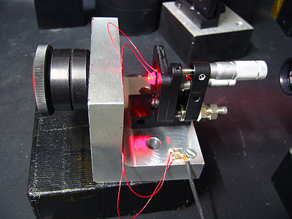
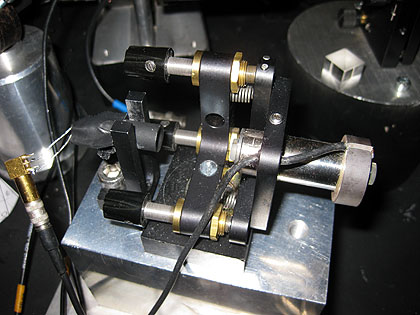
Right pic: improved, more stable version
That's a later version, with an extra pinhole in the resonator that can be adjusted via a an old 3D stage:
Spectra Physics dye laser pump mirrors
As said, the availability of suitable small-radius dielectric mirrors on eBay was for me the key to build an SFPI. The seller still seems to have hundreds of them. Most suitable are the G3854-001 for both HeNe and 65Xnm laser diodes, because they are output couplers with nice anti-reflection coating and have more ot less just the right transmission. There are many other mirrors available, and fortunately Sam maintains a quite extensive list of Spectra Physics part numbers. It turned out that the only small radius mirrors for green and blue I could get hold of are the types G3845-002 and G3845-003. The main drawback is that they are HR's and so have a frosted back side - something with prevents a direct use in a SFPI. I first tried to polish them, to no avail. On the other hand, index-matching away the frosted side by gluing a small piece of 1mm thick glass on top of them does work reasonably well! Thanks to "Geso" for providing a few superb anti-reflex coated glass plates for this purpose. Using a Dremel diamond cutter wheel I cut out a few small pieces (like 8mm x 8mm) from the plates and carefully glued them on the frosted side of the mirrors with optical glue - voila, the frostiness disappeared, giving rise to a nice shiny back side of the dielectric mirror! However, one needs to be very careful in not trapping some air bubbles or other dirt underneath, which would ruin the mirror. Effectively, only a small center portion (like 1-2mm dia) will ever be used, so that's not too tough to keep clean.
First thing with the retrofitted mirrors in hand was to measure their transmission. Unfortrunately, the mirrors are not optimal, being HR's means that they tend to have little transmission. Well, that's at least better than having too much of it.... Here is a preliminary list of transmission data I measured:
| Mirror | ROC (mm) | 488 | 514 | 532 | 633 | 658 | frosted? |
| G3854-001 | 43 | - | - | - | 0.5% | 0.12% | |
| G3845-006 | 50 | - | - | - | 0 | x | |
| G3845-002 | 50 | 0.15% | 4% | 60% | - | - | x |
| G3845-003 | 50 | 1% | 0.005% | 0.025% | - | - | x |
Note added: I now used a pair of G3845-003 with index matched backside with
good success at 532nm, see below.
It also works for 514nm reasonably well with excellent resolution but with quite
a weak singal; not so for 488nm where the resolution is bad.
G3845-002 should be perfect for 488nm, but for some unknown reason, it just
marginally works (very weak signal).
Works perfectly for 496nm and not at all for 514nm, 532nm.
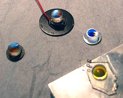
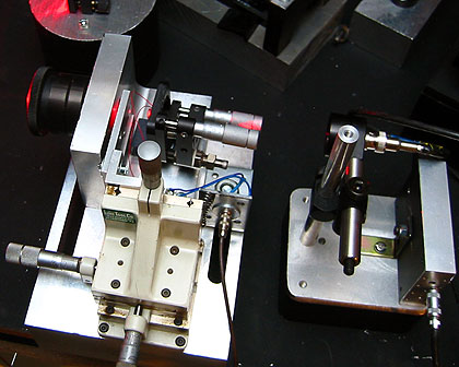
Left pic, on top: index matched G3845-003 glued on small AR glass piece, this in itself glued on the piezo element, which itself is soldered to a small washer, and this is glued onto a 1 inch washer that fits right into a kinemetical mount. Bottom right: frosted backside of a G3845-006 becomes clear upon index matching.
Right pic: mirror and small piezo mounted in one of Geso's wonderful mirror mounts. Shown is also a module involving a large size piezo element, onto which an index-matched G3845-002 mirror is glued.
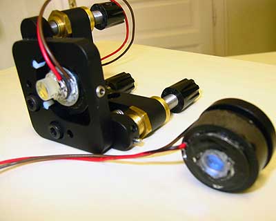
My friend geso has sent me an improved design, which consists of the same mirrors and piezo elements described here, but glued onto an invar tube with fixed length (note invar has like 1/20th of the thermal expansion than aluminum). The tube is mounted in an adjustable holder to control tilt. It needs a little cut and try to figure out the proper distance between the mirrors, including of the thickness of the glue, as this needs to be very precise. But once this is done, this gives a very stable and easy to use device which has specs as good as commercial ones (less than 10Mhz resolution).
Here is a picture:
The photodiode sits in the small tube to the left, and at the right we see the entry mirror glued onto the piezo element. Not seen is a FL=200mm focusing lens to the right, as well as an OD4 neutral density filter that suppresses backreflections to the laser.
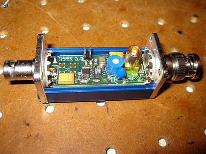
In order to use such a high attenuation requires a very sensitive photodiode amplifier, and along the way I designed a dedicated circuit for it:
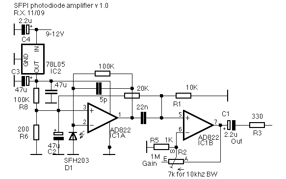
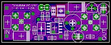
It fits into a small shielded housing which takes up little footprint on the table:
I have some PCBs left over and can assemble more of those amps for people in need for it.
Return to home page
Vers 1.3 -12/09