Return to home page
General Remarks
For holography applications, one of the crucial features of a given laser is its coherence length. It determines the maximal depth a hologram made with the laser can have. For more information from this perspective, see the Holowiki. In brief, the coherence length is determined by the longitudinal mode structure, and therefore one can determine whether a given laser is good or not for holography, by determining its mode spectrum and the stability thereof (and of less importance, its line width).
For lasers with large cavities, the mode spacing is small (a few 100'sMhz) and the best device to measure it is a scanning Fabry-Perot interferometer (SFPI). Most measurements below were done with my home-made SFPI described in the link, and the piezo and mirror data that are sometimes given refer to that page.
On the other hand, for small lasers with small cavities, eg DPSS lasers and especially laser diodes, the mode spacing of many Ghz is too large in order to be well captured by a SFPI (because the display becomes ambiguous as the modes "wrap around" it, and one would need a mirror spacing of a mm or so to prevent this); while one can see whether there are extra modes present or not, it is hard to judge their spacing, and thus, the actual coherence length. For such lasers, a grating based spectrometer is better suitable, and see here for a (partially) home-made device.
Right now I didn't yet obtain a lot of results using the grating based spectrometer (other than testing it), and its main application will be a thorough analysis of red laser diodes. Since this is a very complicated subject, and the reason for having the spectrometer in the first place, I devoted this page for specifically discussing spectral and stability properties of red diodes. It is expected to grow slowly over time.
Testing a 633nm 6mW HeNe laser
My scannning interferometer worked textbook-perfect for my small HeNe laser (unknown brand, ca 6.5mW). A few things could be learned:
I also recorded a little movie
(QuickTime, 0.6MB) that shows how the mode drift builds up the above picture.
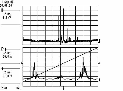
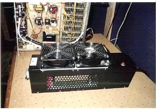
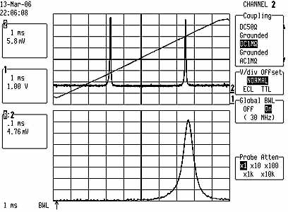
Testing a Mitsubishi ML120G21 658nm 80mW laser diode
Note added: since this is a very involved story, I devoted this page for specifically discussing spectral and stability properties of red diodes; it supersedes the following considerations.
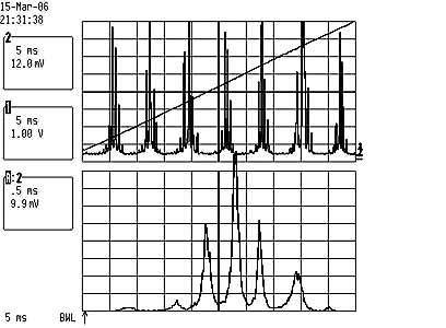
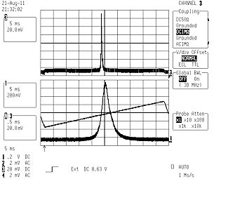
Left pic: chaotic laser diode output, when in unstable regime.
Right pic: super-clean spectrum of stable output, signalling
single longitudinal mode operation.
Bottom lines indicate ramp voltage of piezo element (ca 300Vpp).
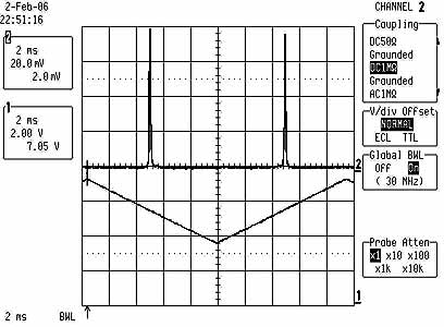
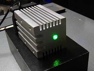
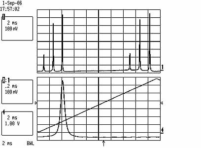
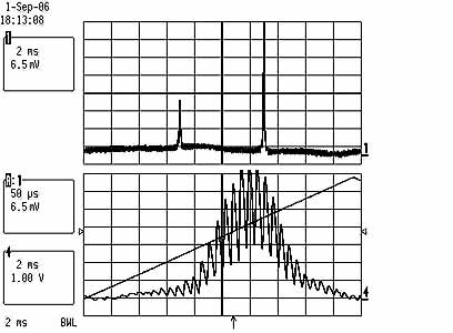
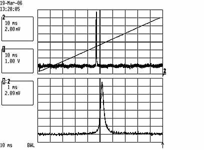
Testing a 532nm 100mW Coherent Compass 315M DPSS laser
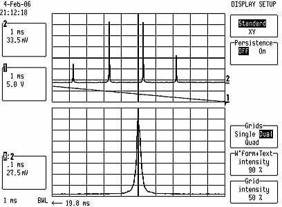
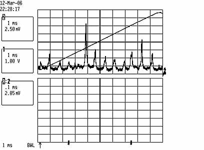
Clean single frequency mode operation of the Compass 315M at close to 100mW,
total span is one FSR=1500Mhz.
Lower scale is zoomed 10 times and shows line width of approx 10Mhz; this means
that the coherence length
is at least 10m or so (probably much more, as the limiting factor on the resolution
is not the laser but the SFPI).
The above applies if the Compass 315M is running in a stable operating zone
(mainly determined by LD current and
temperatures of KTP, resonator); see the notes in the Compass
315M measurements section.
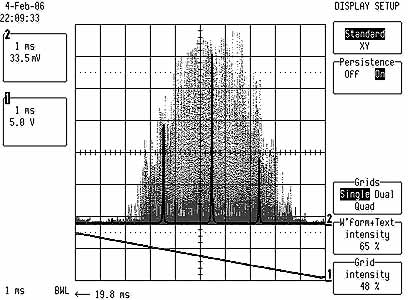
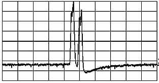
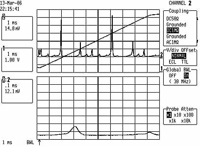
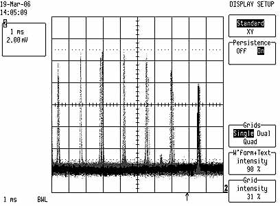
Below is a picture of the laser running in an unstable region where several
modes are present:
The zoom shows a fine substructure that I can't well explain, there seem to be some chaotic oscillations.
Here is a short QuickTime movie
that shows the jumping of the modes when the KTP temperature is slightly changed,
in an unstable regime. It shows that this fine structure only appears when there
are two peaks present within one FSR,
which is consistent with my interpretation.
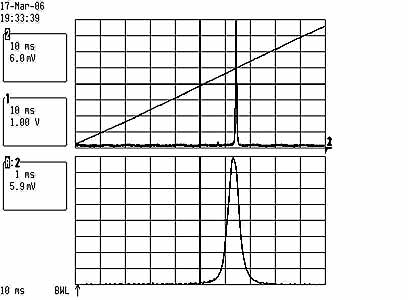
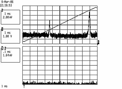
Testing a 532nm 100mW GBS-100 DPSS laser
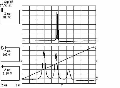
Left pic: Shown is two copies of the spectrum within one FSR=1.5Ghz; this corresponds to approx 200Mhz/Div. However, the apparent mode spacing of ca 200Mhz cannot be true, because this would correspond to a resonator length of roughly 1.5m. Rather, I think what is shown here is a multiply wrapped spectrum, for which the mode spacing is N*1.5Ghz+200Mhz, where N is unknown and hard to determine with the SFPI. Thus the coherence length is effectively at most a few cm only; the line width of a single mode (shown below at 10x zoom) is smaller than approx 10Mhz, which is good.
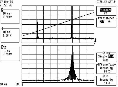
Right pic: While warming up, the mode spacing changes considerably, and at some point the three modes even appear to cross each other. Shown is here a single copy of the spectrum where the mode spacing appears to be only ca 30Mhz, which is impossible. The strong temperature dependence of the spacing supports the interpretation that the spectrum is displayed in a wrapped manner so that the spacing is N*1.5Ghz plus a small amount. In this way, a small relative change in the spacing (due to warm-up of the resonator), translates into a much larger apparent change.
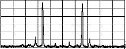
I could reproduce the three modes with my CCD spectrum analyzer, and they look as follows:
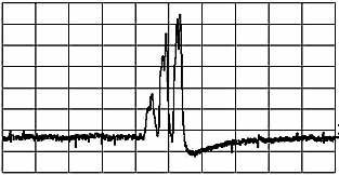
Horizontal scale = 0.3nm/div, so the mode spacing is like 0.15nm, which amounts to 20Ghz and thus, to a coherence length of approximately 1.5cm.
Testing a 532nm 5mW DPSS Picotronic Module DD532-5-3
I could reproduce the two modes on the right with my CCD spectrum analyzer, and they look as follows:
Horizontal scale = 0.3nm/div.
Testing a 532nm 10mW DPSS laser pointer
Testing a 488nm 100mW NEC GLG3105 air cooled argon laser
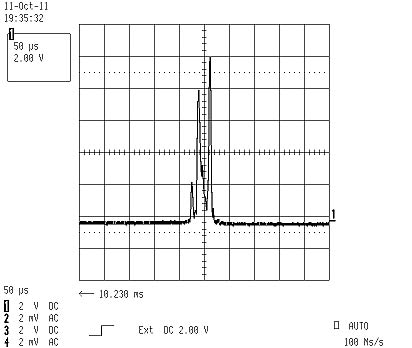
This picture shows a quite messy multi-longitudinal mode output.
The scale is approx 350Mhz/div, and this fits well to a longitudinal mode spacing
of 510Mhz (29.5cm res length).
The picture covers slightly more than two FSR=1.5Ghz, so we get two repetitions
of the same spectrum.
Actually the story is more complicated than that: there are many secondary
peaks,
and despite these look like if they would come from a misaligned SFPI, their
distance does
not change when changing the mirror spacing. Thus they really must be due to
modes coming from the laser.
Note that the FSR is approx 1.5Ghz which is pretty accurately three times the
mode spacing (510Mhz) of the laser.
This means the laser modes outside a free spectral range will map back pretty
closely onto the lines within one FSR,
within approx 30Mhz, and this is indeed consistent with what I find for the
spacing of the smaller peaks!
(see the 10 times zoomed lower part of the pic).
So all this is consistent with a multi-longitudinal mode output spanning many Ghz, and thus, with just a few cm of coherence length.
Testing a Lexel 88 Argon Laser
------------ 488nm:-------------
Left picture: multi-mode output at 488nm with careless adjustment
of the etalon.
The distance between the peaks corresponds to approx 200Mhz, which is the mode
spacing of the laser cavity.
Right picture: even careful adjustement of the etalon does
not fully get rid off the extra modes.
The scan captures about two FSR=1.5Ghz, so the large peaks are multiple copies
of the same line.
------------ 496nm:-------------
Clean single frequency output at 496nm. Upper part: ca 350Mhz/div, lower part: 35Mhz/div.
------------ 514nm:-------------
Left picture: Single frequency output at 100mW. The scan width
is one FSR=1.5Ghz, and from the lower
zoomed part with 15Mhz/div we see a line width of approx 5Mhz. Thus the finesse
of the SFPI
is in the order of excellent 300! This also means that the coherence length is at least in the order of several tens of meters.
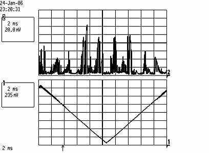
Right picture: By slowly tilting the etalon, the laser jumps
from one longitudinal mode to the next.
Shown is a scan over these modes obtained in this way.
Their spacing is f=200Mhz,
which corresponds to the resonator length L=76cm of the laser (f=c/(2L)).
Here is also a brief QuickTime movie
that shows how these mode jumps were recorded.
It displays nice stable single mode operation near 488nm at 20mW, practically over all power settings. Shown below a pic of the scanning interferometer output:
Lower trace is 10-fold zoom of upper trace, ie, approx 20Mhz/Div. The line width thus is in the order of at most 20Mhz, and so the coherence length at least several dozens of meters!
For some further details see here.
B&W Tek BWB-475-10-OEM DPSS laser
I got one of those "out of specs", it hat 5mW at 475nm, instead of 10mW. As expected the nice little thingy runs multimode and thus is unusuable for holography purposes. Shown is the output of my CCD spectrum analyzer:
Return to home page
Vers 1.3 -10/11