
Return to home page
This project grew out from investigations of the spectrum of red laser diodes. This is motivated by our attempts to develop a stable red diode laser module. As it turns out, the mode spacing of a laser diode is in the order of 100Ghz (corresponding to an approx. 0.1nm gap at 600nm), which is too large to be unambiguously visible by a scanning Fabry-Perot interferometer. On the other hand, such a resolution is obtainable by better grating based OSAs. So I thought it to be worth a try, and got a few surplus devices from ebay, in order to check their suitability for this purpose.
In short, the Rofin-Sinar RSO 6000 scanning monochromator turned out not to be well suitable due to lack of sufficient resolution (without modifications at least), while the Optical Engineeering 16-B-H-F does well, especially after augmenting it by a linear CCD sensor. This modification and the electronic control circuit are described below.
A simple explanation of how these devices work is given at Wikipedia. The following picture, linked from there, shows more or less all what is important:
The Rofin-Sinar RSO 6000 is a scanning monochromator for which the grating D is rotating and a photodetector is placed behind the exit slit F. For the Optical Engineeering 16-B-H-F the grating D is fixed and a readout scale is placed at location F. My modificaction consists in replacing F by a high resolution linear CCD sensor array so that one can read out the spectrum electronically, and display it on an oscilloscope or computer screen.
More detailed information on OSAs and gratings can be found as usual in Sam's FAQ, and also here.
Optical Engineeering Model 16-B-H-F
To my initial disappointment this turned out to be a model for the infrared, and I wondered whether it could be of any use; but it turned out to be one of my best investments ever. It is a very simple device, consisting essentially only of a grating with 300 lines per mm, a variable (mininum approx 50um) slit, and a few mirrors. The path between input slit and grating (same as path back to the readout scale) is folded a few times and its total length is 114cm, which gives a good resolution. The readout scale is calibrated for approx 3um and has some kind of (zinc sulfide?) fluorescent surface for viewing it. It is illuminated by a UV tube which also lights the scale.
An overall view is shown below; attached on the left side (below the readout scale) you see a parabolic mirror which images the input slit onto the readout:
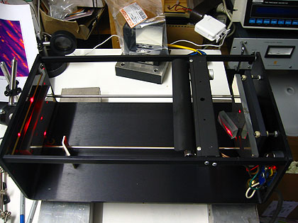
Fortunately, visible radiation can be viewed directly at higher diffraction order. The long path length and the good optics in fact turned out to be a blessing. Out of the box the resolution turned out to be better than 0.1nm, which is enough for seeing multiple modes of a diode laser, even with the naked eye! Its absolute accuracy, referring to the attached scale, is in the order of 0.2-0.3nm (judged from a HeNe line). More precisely, in 5th diffraction order the wavelength spread is approx 8nm/cm, or 1.25mm/nm, and the 50um slit yields then a resolution of approx 1/20nm.
Probably a device with similar properties can be built simply by using a DVD as grating, a parabolic telescope mirror and two razor blades forming the slit.
Upgrade to LFL1402 Linear Photodiode Sensor
At first I have modified this device by placing a small linear photodiode sensor iC-LFL1402 at the position of the focused exit beam (the sensor has 256 pixels and is functionally equivalent to the TSL1402R by Taos). After having built a simple circuit for generating the clock and "start integration" pulses, all what was needed was to connect the output to a scope (the circuit is quite similar to the one described here, just adapted to parts I had lying around). The resolution of this sensor is about 50um per pixel, which fits to the slit size of the spectrometer. The total resolution of this system is thus approx 0.05nm. This is not at all bad for such a simple device and well sufficient to identify multiple longitudinal modes of a laser diode.
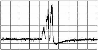
Below are shots of the RLD65PZB5 Rohm diode at randomly chosen operating points. A more systematical analysis is presented here.
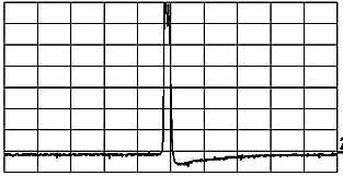
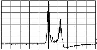
To the left: clean single mode operation. To the right: two
modes are visible.
The horizontal scale is approximately 0.3nm per div, and the resolution is
about 0.06nm/div;
this corresponds to the 50um slit width.
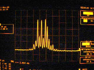
Already with the original 50um slit, even longitudinal mode spectra of small DPSS lasers can be resolved:
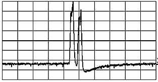
To the left: GBS-100 100mW DPSS laser shows three modes, confirming the analysis with the scanning interferometer.
To the right: dual mode spectrum of a 5mW DPSS
module.
Upgrade to high resolution Sony ILX553B Linear CCD Sensor
Desiring to improve on the resolution, I got a Sony ILX553B linear CCD sensor with 5150 pixels and 7um pixel width. I also got hold of a 10um slit, and was able, upon careful adjustment of sensor, slit and grating, to improve the resolution to better than 0.01nm which corresponds to 2 pixel widths. A minor inconvenience of the sensor is its high sensitivity (so it quickly saturates, even from low ambient light), and a relatively poor dynamical range of 1:200 or so.

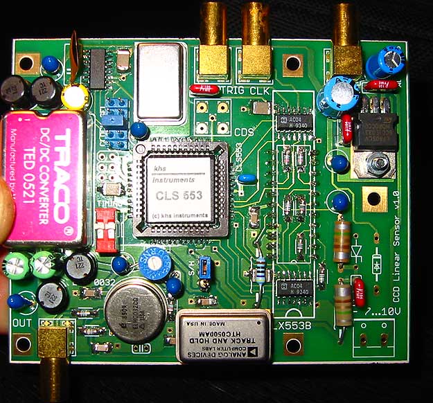
I have put together a circuit and designed a printed circuit board to drive the ILX553B linear CCD sensor by using a CSL553 custom programmed microprocessor, which otherwise would be quite hard to do without major efforts (due to the complex timing needs of the control signals). The circuit is close to those of the datasheets, except that I added a few peripheral devices I happened to have around, in particular an fast HTC0500AM track-and-hold circuit, which is necessary because the CCD does not have a sample-and-hold feature by itself. Moreover I added a fast opamp for eliminating the large offset (approx -5V) at zero light, a quartz oscillator and frequency divider for adjusting the clock rate, plus a heavily filtered DC/DC converter so that one can run the circuit off a single supply (7...10V at 0.5A or so). The CCD sensor is mounted on the backside, so that one can fix it flush with the spectrum analyzer's focal plane.
Below a pic of the pulse timings (the control pulses of the CCD coming from the CLS553 are even more intricate; I recommend this description of how such CCD sensors work). On the upper trace there is the CCD sensor raw output. The actual signal consists of the "valleys", whose depth varies. The second trace shows the clock signal that enters the sample-and-hold-circuit: only when it is low the raw output from the upper trace is sampled, and this happens precisely in the valleys. When it is high the output is held constant. The (inverted) result is the third trace, which is the desired output. One microsecond corresponds to one pixel width of 7um size, and this corresponds to a wavelength resolution of approx 6pm=0.006nm (which translates to frequency resolution of 4.3Ghz/pixel at 650nm; I confirmed this by measuring the frequency shift of a laser diode that was independently determined by a scanning interferometer). This means that the longitudinal modes of a resonator with a length less than 3.5cm can be resolved.
The circuit diagram is here, and the PCB in Eagle-format is linked to the image above. The schematics does not show all the bypass caps on the PCB; the undesignated polarized capacitors are tantals of a few uF, while the unpolarized ones are ceramic bypass capacitors of 100nF or so. Note that the pins "Phi1" and "Phi2" of the CLS553 controller chip are exchanged with respect to what is written in its data sheet, as I had to find out the hard way. The updated versions of PCB and schematics take this into account.
There are provisions to change the pixel clock speed (nominally 1Mhz) by jumpers (JP2), to provide external timing (JP1), and to change the exposure time manually by a switch (S1). The "OUTPUT" needs to be connected to the y-axis of an oscilloscope, while "FRAME TRIG" is used to trigger the x-axis. There are two more outputs for optionally playing with "correlated double sampling" for noise suppression (not needed for the present application). There is also a jumper for bypassing the sampling-amd-hold circuit, for testing purposes.
The CSL553 controller chip and ILX553B CCD sensor were conveniently obtained from Framos and Eureca, respectively. The latter company has a large selection of linear CCD sensors and data sheets; if I would build such a circuit again, I would use a different sensor with less resolution (eg 14um, which would be sufficient), but with an integrated sample-and-hold circuit and plus a shutter. There exist also sensors that do not need an external processor for timing, which may be preferable as well. See the datasheets at Eureca.
Here a brief movie showing mode instabilities when a laser diode current is increased by a few tens of milliamperes.
You see a single mode zone being crossed a few seconds after the scan starts:
(the resolution of the still picture is 0.12nm/div, and of the movie 0.3nm/div).
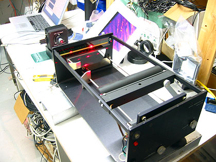
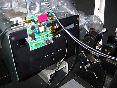
Here a pic of the completed controller in action, attached to the outside of the analyzer:
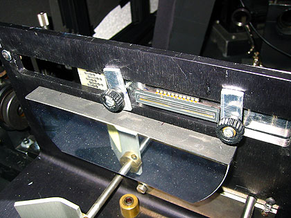
Finally, a look of the CCD sensor (between thumbscrews) as seen from the inside; the parabolic mirror is below:
Return to home page
Vers. 1.1-12/06