Return to home page
Return to ECDL diode tests page
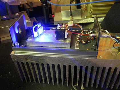
The first diode I checked works surprsingly well SLM to 50-60mW in free running mode, and next thing was to check its ECDL potential in a test setup. The first results were disappointing, where I used grating #1 as defined on the ECDL test page, vertical polarization and a Lens-27 for collimation: the single mode zones didn't extend beyond the free running SLM zones, and the power was less while the stability was worse. However the next try was better, where I used the well-known Aixiz A-HGL-905-3H collimator (made for 405nm) and grating #3 which gives more feedback:
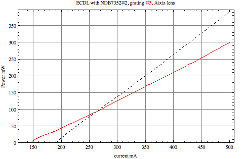
Here a comparison of the power levels (the dashed line refers to the free running diode):
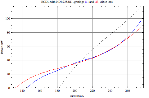
We clearly see how the lasing threshold is significantly reduced by the feedback of the gratings. Moreover we see a plateau until approx 60mW for which single mode operation is frequent, and the rising slope beyond that seems to reflect that the diode then predominantly runs multimode, with higher efficiency.
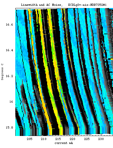
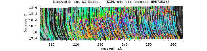
The second diode I tested under the same conditions turned out to be generically worse, consistent with its free-running behavior. However, after very carefully adjusting the collimation, choosing longer resonator and also slightly vertically tilting the grating, single mode regions were found even up to more than 200mW:
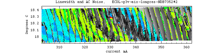
Here is the plot of output power (the dashed line refers again to the free running diode):
Another test was made with grating #4, which has considerably less reflectivity. First a long resonator was chosen (see the narrow spacing of the mode jumps), and the systems was very unstable even at low currents, apparently because there was not sufficient feedback:
Then a as-short-as possible resonator was chosen where the feedback is stronger, and the system turnd out to be much more stable. It turned out that even in regions with noise, the system was mostly single mode plus some weak extra modes. The complete absence of noise quite reliably indicated single mode operation in this case:
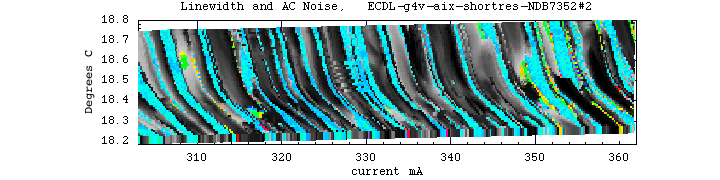
This seems a quite useable configuration, since a simple noise detector is sufficient to detect single/multimode operation. We see again, ECDLs are tricky and require a very carefully matched configuration, for each diode, and minor changes in the adjustments can have a major effect on overall stability.
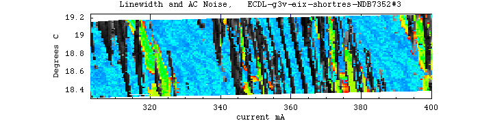
Even better turned out a test for diode #3 in a short-resonator configuration with grating #3, which achieved more than 200mW quite stable single mode in the first try:
Feedback with simple glass plate
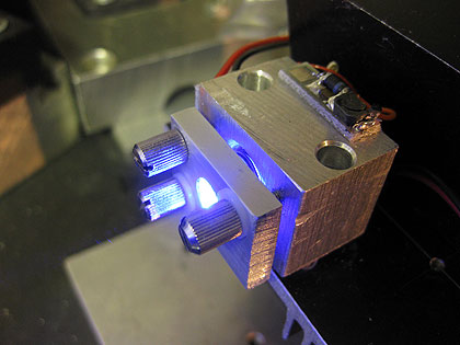
There were interesting reports here and here that actually a simple glass plate may provide enough feedback in order to stabilize the 445nm diode to single mode operation. Needless to say would is very intriguing as one may get rid off the grating. So I have tried two versions, namely with a simple disk and with an wedge plate, both uncoated fused silica of 1mm thickness. The wedge plate separates the reflections of the front- and back sides, which may be a good or a bad thing ;-) Thus it effectively reflects approx 3.4% back, and the ordinary plate 6.8% modulo interference effects. Correspondingly I found that the wedge plate reduces the threshold current by approx 10mA and the ordinary glass by approx. 20mA. I coulnd't reduce it by like 40-50mA as in the reports, where an uncollimated beam was used -- I use an Aixiz 405nm collimator. Also I found that my mounting wasn't precise enough for just having the glass flat-on the mount, so I needed to make the glass plate adjustable; here is a pic of the test setup:
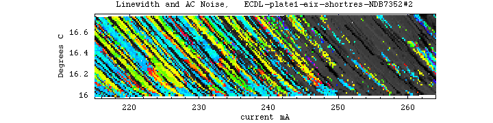
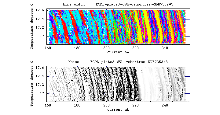
Here is the result of a current-temperature scan for the wedge plate:
and here for the ordinary glass plate:
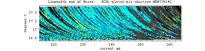
We see that when there is feedback from both sides of the glass plate, single mode operation is predominant up to approx 250mA (80mW), and then increased noise and instabilities appear. It seems that the relatively weak feedback (6.8%) stabilizes the laser where essentially one supermode wants to lase, while at higher currents the appearence of several incoherent supermodes cannot be suppressed.
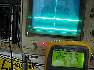
Below is a movie (3.3MB) that shows the spectrum when ramping the current up and down again; the increased noise and instabilities are easy to discern. Note the acoustical feedback at certain points, it arises due to the laser acting a a microphone:
Finally I made an effort to try a very short resonator, with the hope that the broad mode spacing would facilitate single mode operation. Alas, in effect I found that at higher currents there is an increased tendency to run extra side modes. Using a very low fl/high NA, high efficiency lens from Swisslas, and a special mount, I managed to get down to a resonator length of about 1cm. The scan looks as follows:
So again we see a transition zone above which the laser tends to run run multimode, though pretty stable without great mode chaos, ie., without much noise.Which is bad if one likes to run the laser with only monitoring the noise. The power around 200mA is about 60mW.
Feedback with thin plate
Following a suggestion by Ahmet to make use of an etalon effect of a very thin plate, I also tried a microscope slide cover glass plate of perhaps 0.15mm thickness. However the problem was to achieve sufficient flatness over the large beam diameter, and the output was predominantly multimode. Perhaps with a proper mounting technique things can be improved (I just glued it over a 5mm hole).
Feedback with "wrongly coated" lens
From the above results I got the idea that even a collimator lens with no coating, or a coating for red, could provide enough feedback for stabilizing the laser. So I put in a collimator with the lens G-650-1, which is coated for red and even has a distrinctively strong blue hue when looked upon. And indeed we see single mode regions beyond 260mA (checks for higher currents are underway):
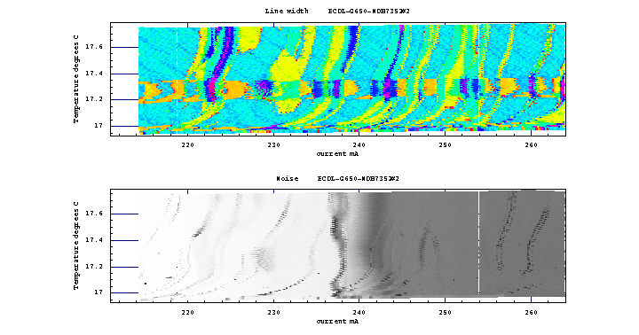
(the pronounced horizontal band is due to a disturbation).
We see that plenty of single mode regions persist, which are widely separated due to the short resonator (perhaps 5mm). Moreover we see that there is, unfortunately, little correlation between multi-mode operation and noise in the light output (that's why I have not placed the plots on top of each other). The phenomenon of strong noise beyond 240mA persists here as well, I need to find out whether it is detrimental for holography or not; so far I couldn't discern any particuliarity in the spectrum apart from weak side modes. There might be a low-intensity noise floor or something like that.
Note also that the power loss was like 50% with this collimator, so alltogether the G-650-1 is not a good option.
Feedback with AR coated plate
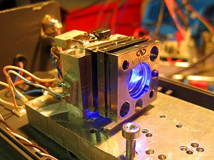
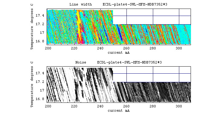
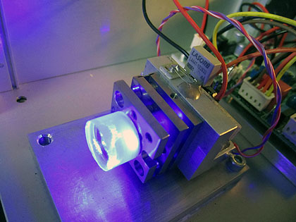
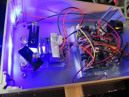
I also tried a 1mm thick plate, AR coated on both sides, of which I estimate the reflection at 445nm to be at around 2%. The resonator length was about 2cm and the Swisslas collimator was used. Surprisingly I could get the threshold down to 148mA at 17.5C, which indicates a much stronger feedback than expected; perhaps the optical quality (flatness?) is better than of the other plates. I also used a much more stable and better adjustable mount, namely a MFM-50 flexure mount of Newport, which can be attached right to the diode mount for maximum rigidity and short resonator length. I found the whole setup quite promising, a test build looks like this:
The scan looked in line with expectations, ie stable single mode operation until ca 250mA or around 70mW; and beyond an increased tendency for instabilities and multimode operartion with isolated but unstable single mode spots up to 200mW and more:
Feedback with etalon
I have a bunch of quartz etalons for argon lasers around, they are approx. 1cm thick and their faces are extremely parallel; they are coated with a bluish tint and I estimate a few percent reflectivity on each face. I placed one close to the diode, with perhaps 2cm distance beween the closest face and the diode. The feedback was very strong, actually I found to most extreme reduction of threshold current I ever have seen, namely from 198mA to 93mA! Indeed the etalon acts as a strong reflector at certain wavelengths, and clearly lasing will primarily occur at those. The net result was disappointing: stable single mode operation was possible to 15-20mW only, above that there were always severel modes, not chaotic but isolated ones. This seems to be typical for too strong feedback.
Feedback with extra slit
So far I found that little feedback stabilizes the diode well only at low currents, while at higher currents chaotic multimode operation occurs, similar to no feedback at all. Stronger feedback pushes the chaotic regime up, but then there nevertheless remains a tendency for having several isolated modes at elevated currents. When tuning through those modes, by changing the current and also simultaneously spectrally analyzing the spacial components of the beam, it appears that many of those extra modes have different spatial patterns, so correspond to different supermodes. So I got the idea to suppress those modes by having strong feedback through a thin slit, which would hopefully favor certain transverse modes and suppress other modes that would otherwise be supported.
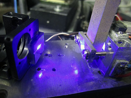
And indeed, first tests were promising, I used a slit with approx size 5mm x 0.2mm near the collimator in a grating ECDL, and immediately found a very clean spectrum! The threshold current was increased from 121mA without slit to 128mA with slit. As expected, the power is reduced and I obtained around 95mW at 350mA, however quite stable so. I didn't tune up higher since a lot of power gets absorbed by the slit and I wanted to avoid damage. The spacial far-field pattern was much better than before, so the transverse modes were drastically reduced. Essentially only the middle horizontal lobe gets amplified and spreads out, so the familar stripe pattern gets suppressed; that is certainly more than welcome! However, several vertical stripes occur, it looks as if they'd come from the slit because they move with it. Perhaps they arise from irregularities of the slit, and could be ameliorated by using a precision slit.
Here a pic of the preliminary setup, The slit is glued onto an aluminum slab that is press-mounted against the diode mount:
When scanning through the current, the mode jumps are very small, unlike for the other setups tested so far. This means that now indeed the longitudinal modes of the extended cavity are predominant and not any more the transversal modes of the diode!
So this seems to be a promising route to go, obviously much more fiddling is needed in order to see how far this can be pushed, as there are now two more degrees of freedom to play with: slit thickness and axial location within the resonator. First of all I need to find a good way to mount the slit in a stable but adjustable manner. Stay tuned.
Here as summary some comparative data for diode #3 in various configurations (at approx 17C, short-fl aspheric lens from Swisslas):
| feedback | refl approx % | resonator length, cm | threshold current, mA |
|---|---|---|---|
| none | -- | -- | 189 |
| fused silica wedge | 3.4 | 2 | 174 |
| fused silica plate | 6.8 | 2 | 169 |
| NFK-5 plate | 8 | 1 | 153 |
| grating #4 | 7 | 2 | 142 |
| grating #3 | 21 | 2 | 121 |
| grating #3 plus 0.2mm slit | ? | 4 | 128 |
| microscope slide cover plate | 8 | 1 | 152 |
| AR/AR coated plate | 2-3 | 2 | 148 |
| Ar laser etalon | few | 2-3 | 93 |
| G-650-1 | ? | few mm | 185 |
For a brief collimator efficiency comparison, see here.
Summary of the NDB7412
For the blue Nichia 1W diode a pretty universal pattern seems to emerge. Relatively independenly of the feeback (within reason), the max. stable output is in the order of 60-80mW; what changes with increased feedback is that the threshold current is lowered, but the onset of instabilites/multimode operation does not improve, rather it tends to occur at lower currents as well. There seems a universal border at 230-260mA above which multimode operation becomes predominant.
What is surprising is that the diodes can be stabilized with very little feedback, of just a few percent, which already leads to a drastic reduction of threshold current. This suggests that the internal reflectivity of the output facet is quite small. It is also surprising that gratings do not perform significantly better; I believe that the wavefront of the diode is so "dirty" that the grating cannot not really play out its advantages. In particular, multiple transverse supermodes are not well suppressed. It seems that this can be improved by inserting a narrow slit into the resonator which suppresses higher transverse modes.
With sacrifices on stability and mode purity, more than 200mW are possible in isolated spots, also relatively independent of the feedback. However, there is then a tendency for several supermodes to lase simultaneusly, which means that there are several supermodes with different frequencies; in other words, different spatial regions of the beam are not coherent with respect to each other, which is diffcult to see if one samples the wavelength at a single spot only (such as in the plots above).
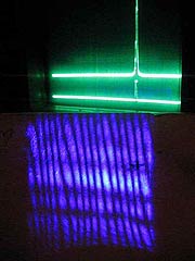
This can be seen by the naked eye in the following movies. They show on the top the display of the CCD spectrum analyzer, and on the lower part an interference pattern from an interferometer (Fizeau-type, just reflecting the slightly divergent beam off a glass slide). There is also a sound track from the noise monitor. The interferometer fringes are the vertical stripes, and the horizontal bands correspond to the transverse emission pattern of the diode (which arise from coherent superposition of supermodes in the broad ridge diode). Both structures jump when changing the diode current.
The left movie shows the spectrum and interference pattern in the region of 200-230mA. One can clearly see the effect of mode jumps and multimode operation on the interference pattern, which then blurs. The important thing to note is that all regions behave in a synchronized manner, ie., all fringes move in the same way. This means that in this region, there is only one supermode lasing, and all regions of the beam are coherent with respect to each other.
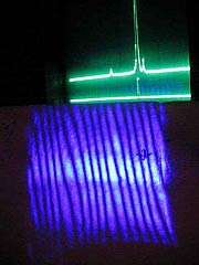
The right movie shows the spectrum and interference pattern at around 300mA, which is beyond the "stability border". We see that the situation is much less stable and often multimode operation occurs. The important thing to note is the various different bands tend not to be synchronized any more, and we see that the fringes in the three major transverse mode bands tend to jump independently. This means that several supermodes lase simultaneously, which are not mutually coherent with respect to each other.
Here a protope which also includes beam shaping with anamorphic prisms:
Return to home page
Vers 3/1-2014