ESP32-based high precision TEC controller for laser diode holography
 Under construction
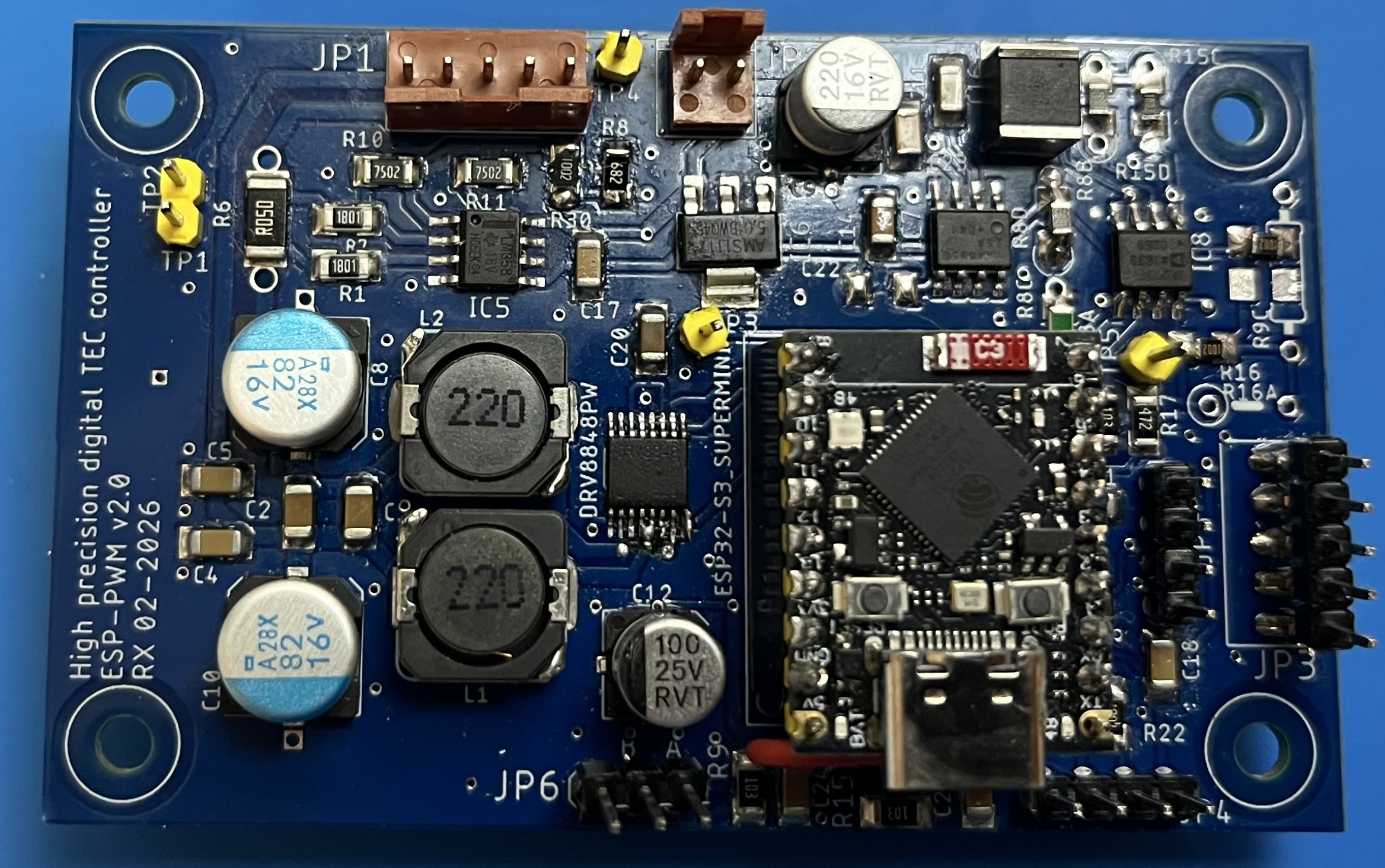
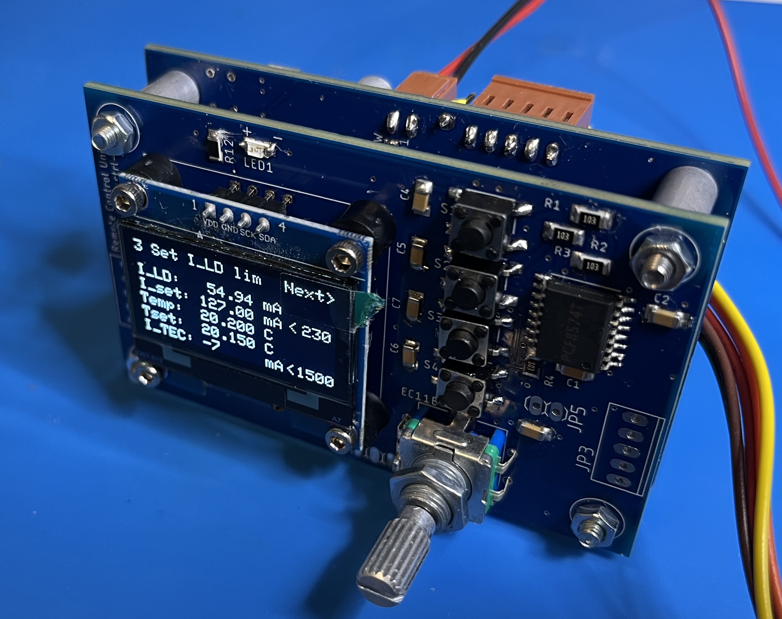
Left: PWM controller board with ESP32-S3 Supermini board attached on the lower right. Right: Control board attached as shield.
This is an evolution of our Arduino based TEC controller, now based on the more powerful and smaller ESP32-S3 Supermini board, which is cheap and easy to get from Aliexpress. While we emphasize the new features below, we will also simply copy-paste text from that page when it fits here. For more background on laser diode holography see here. The advantage as compared to an analog circuit is broad automatic adaptability with regard to control loop (PID) parameters, easy remote control, protection features, completely getting rid of potentiometer/trimpot drift, and dual (heating and cooling) drive capability using a bi-directional PWM H-bridge. This version is smaller than the Arduino board and ought to fit into laser heads. It's maximal TEC current is about 2A, depending on heat sinking. My plan later is to make an update for the laser diode (LD) driver later too, either on a separate board or on an enlarged board that hosts both TEC and LD controllers.
To be clear: the primary purpose of this controller is to temperature stabilize laser diodes for holography. The intended heat loads involve laser diodes with up to about 500mA drive. This requires stability to about 1mK = 1/1000 degrees C, tied to a specific kind of thermal load, for a relatively narrow temperature range. Also, tuning does not need ultrafine steps, it is more important that a given temperature is kept stable for extended periods of time. This allows to use a rotary encoder which provides much higher stability than using any kind of potentiometer. So explicitly, the controller is not optimized for ultra-fine scanning over temperature (like for spectroscopy), but when utilizing external digital control, it can perform small steps in the mK range too.
So here are the specifications:
- "ESP32-S3 Supermini" module attaches to PCB, makes soldering easier.
- full H-bridge for bi-directional TEC drive
- 12V unipolar supply
- up to +/-2A current; intended Peltier sizes about 10x10mm to 20x20mm
- standard 10k Thermistor for sensing
- setpoint range about 10-15 degrees C, modifiable by choosing different resistors
- temperature stability ~ 1mK for hours if undisturbed
- noise level < 1mK
- PWM ripple about xxx mV_pp at 50:50 duty cycle //to be measured
- precision current control/monitoring via dedicated sense circuitry
- auto turnoff for open/shorted thermistor, temperature out of range, and H-bridge overtemp
- digitally configurable are: temperature, TEC current limit
- "autotuning" PID control loop configuration, including "regulator windup" prevention
- remote control via USB serial terminal, or LabVIEW.
The configuration can be stored in EEPROM and once set up, the controller can also run without external connection.
However the intended mode of operation is to use it with the
- separate SH1106 type 1.3'' 128x64 OLED display board with push buttons and rotary encoder
- ready interface for companion laser diode driver, with programmable laser current, current limit.
Notes about the hardware design
- ESP32-S3 Processor:
To keep the size as small as possible while keep handling simple, I chose the "ESP32-S3 Supermini" board. The S3 version is necessary because the more common C3 and other variants do not offer the high precision hardware PWM motor controller (MCPWM) that is needed here. It works well but there are a few compromises.
First, despite of the high CPU frequency of 240Mhz it does not output a stable enough high resolution hardware PWM signal beyond 120khz, so that's just double as compared to the Arduino with 63khz. This implies large caps and inductors for filtering, as for sensitive holography applications any noise coupling to the laser diode must be kept to a minimum. There is also a limit from the H-bridge, however the one I chose can do up to 250khz without problems.
Second, the external pins on the ESP32-S3 Supermini board are quite limited -- many pins are reserved for other purposes and cannot be used freely. That generated later a problem: originally I intended to control the whole board from another board carrying an OLED display, push buttons and a rotary encoder via the I2C bus. It turned out that the intricate timing constraints of the MCPWM sub-unit interfere with the timing of the I2C bus, to the effect that the rotary encoder works very choppy. After months of playing with all sorts of interrupts I gave up and had the rotary encoder connected directly to the processor. There were no more freely usable pins on the Supermini board; however there are extra solder pads on the back side of the board, not connected to the pin headers. So two of these must be connected by wires by hand (together with the 5V supply which may NOT be connected to the 5V pin (!), rather it must be connected to the "+ Bat" solder pad on the back side). So all-in-all, there are 3 extra wires from the Supermini board to the PCB, see the BATT, GPIO17 and GPIO18 connections in the schematics below. Clearly, that's a hack but I didn't see a better solution if one wants to keep the small Supermini board. - H-Bridge: I chose the motor controller H-bridge DRV8848WP, which is quite small but can deliver, supposedly, 4A continuously when in parallel mode. It has a build-in thermal protection, which is sensed by the ESP32. I found it hard to push it beyond 2A with cooling via the PCB, even when attaching a small heat sink on the back side. Restricting to 2A should be sufficient for our purposes, while maintaining a comfortable overhead. Avoiding excessive heat on the PCB is beneficial for stability anyway.
- High sensitivity requires a front-end with a precision rail-to-rail opamp, I use OP213 but eg. LTC1013 should also be fine.
- A precision 5V low noise reference is supplied by an external chip, a wide range of choices is possible depending on stability requirements (eg., from Ref02C to Ref5050 to MAX6250).
- DAC: Since today there are cheap 16bit ADC chips, dithering as done for my previous Arduino board is not necessary any more, and I use the ADS1115.
- Main concern is how to keep short term stability in a high-noise PWM environment. This requires a careful PCB layout, avoiding noisy couplings and ground loops. This applies in particular also to external connections.
- Remote control: While the ESP32-S3 offers Wifi/BT connectivity, I didn't manage to usefully integrate this without upsetting the delicate hardware MCPWM timing system. Thus if remote control is desired, either via serial command line or LabVIEW, it must be via USB for the time being. However, the idea for this driver was to be remotely controlled by a separate small board with
- OLED display , including control buttons and rotary encoder. It can be either directly attached as a shield or connected via cabling (not too long because of I2C bus).
-
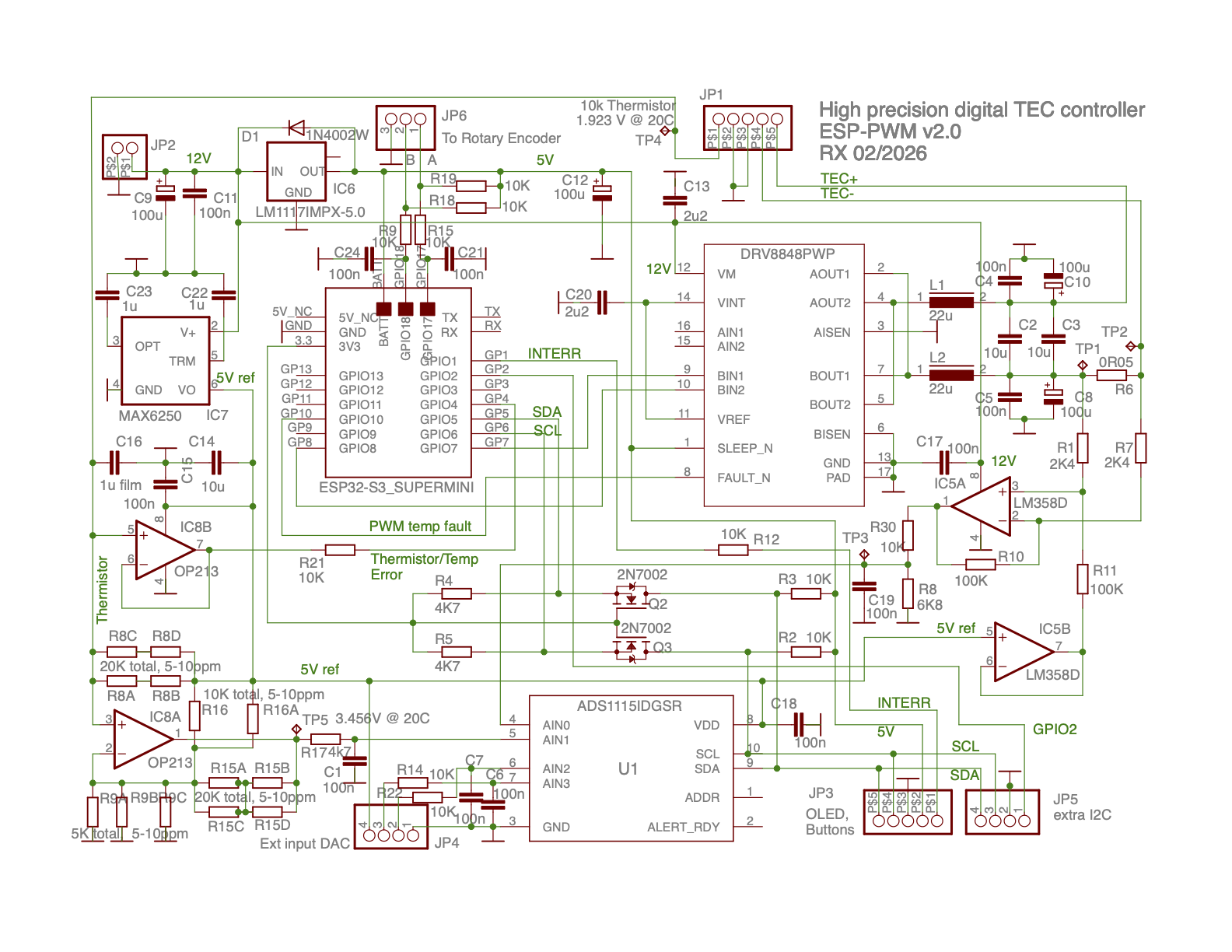
Here are the schematics, click for higher resolution:
Comments on the schematics:
- JP1 connects to TEC element and associated 10k thermistor, JP2 connects to 12V power supply, JP3 connects to the optional remote controller board with buttons and 1.3'' OLED. JP4 connects to voltage reference and two16bit DAC inputs and JP5 connects to the I2C bus allowing to attach optional other devices if needed, eg. a laser diode driver, also it accesses GPIO2 of the ESP32. JP6 connects to the rotary encoder.
- BATT, GPIO17 and GPIO18 connections are on the back side of the ESP32-S3 Supermini, so must be connected by wires to the 3 pads on the PCB.
- The better the 5V reference, the better the stability. Probably for many applications a simple Ref02C would do, however if one wants to add later the laser diode driver shield, a highest stability and lowest noise reference is desirable. Note that the wiring for some other references can be different, that's why there are redundant caps C22, C23.
- I prefer 5V instead 3.3V which yields a better signal/noise ratio for the sensitive ADC, and also it fits better to the parts I have. It also fits better to the +BAT connection to the ESP32-S3 Supermini. The price to pay is a 3.3V to 5V level shifter for the I2C bus, as the ESP32 connects to 3.3V. In principle one could run all also on a 3.3V reference, by adapting IC6 and IC7 and shorting the level shifters Q2, Q3.
- For optimal stability, C16 should be a foil capacitor.
- C8, C10 should be low ESR caps with high ripple tolerance.
- C2, C3 are ceramic, 2x 10u in parallel
- IC8B is used to detect open/shorted thermistor, or temp out of range due to runaway etc.
- Resistors
R8, R9, R15, R16 should have high stability, low noise and most importantly, low tempco, like PTF-56 5...10ppm/C 0.1% resistors. Also 1206 SMD precision resistors can be fitted on the board. It allows to put various combinations in series and/or parallel configurations , which permits to use readily available resistors. Many temperature ranges are possible by using different resistor configurations, and some sample configurations are listed below and in the code. Here are some standard options (all can be realized purely with 10k resistors except Version 12) that are already
preprogrammed in the code and just need to be compiled in software with the corresponding flag set:
- Version 10: R8 = R9 = R16 = R15 =10k: Range ~12-38 degrees C (wide span gives less stability)
- Version 12: R8 = 12.5k, R9 = R16 = 10k, R15 = 20k: Range ~15-27 degrees C (my pref)
- Version 20: R8 = R15 = 20k, R9 = 5k, R16 = 10k: Range ~18-28 degrees C (as in schematics)
- Version 21: R8 = 20k, R9 = 5k, R15 = R16 = 10k: Range ~13-32 degrees C
- Version 25: R8 = 25k, R15 = 15k, R9 = 5k, R16 = 10k: Range ~12-25 degrees C
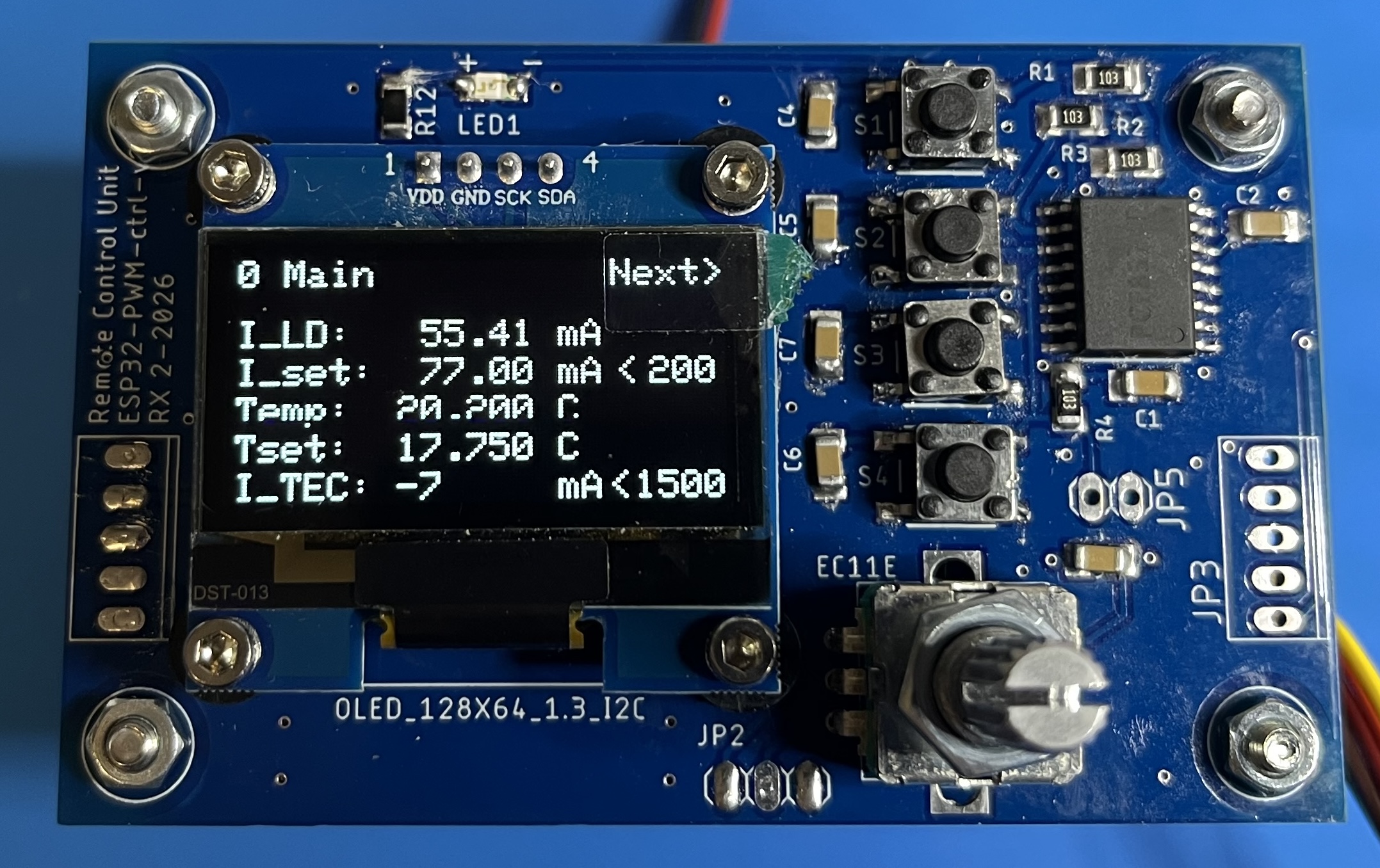
- It can be used as a shield on the backside of the TEC controller board, or connected via wires to JP2, JP3. In the picture also laser diode current and its limit are displayed, which is not yet fully supported. The TEC controller board can be operated without this board if one uses remote control via USB.
- There are four buttons, top: next menu, 2nd: store, 3rd, recall, 4th laser on/off. The button of the rotary encoder allows 1:10 fine tuning.
- The board uses a PCF8574 port expander to control the buttons via the I2C bus (JP3). Unfortunately, controlling also the rotary encoder via I2C interferes with the hardware PWM timer of the ESP32-S3, this is why the encoder must be connected directly to the ESP3-S3 via JP2. JP5 allows to interact with the PCF8574 as an option for extra buttons etc. There is also a little LED that is controlled via the PCF8574.
- A standard SH1106 type 1.3'' 128x64 OLED display can be put directly on the board; in principle, other I2C OLED displays could be connected by wires.
- The schematics are here:
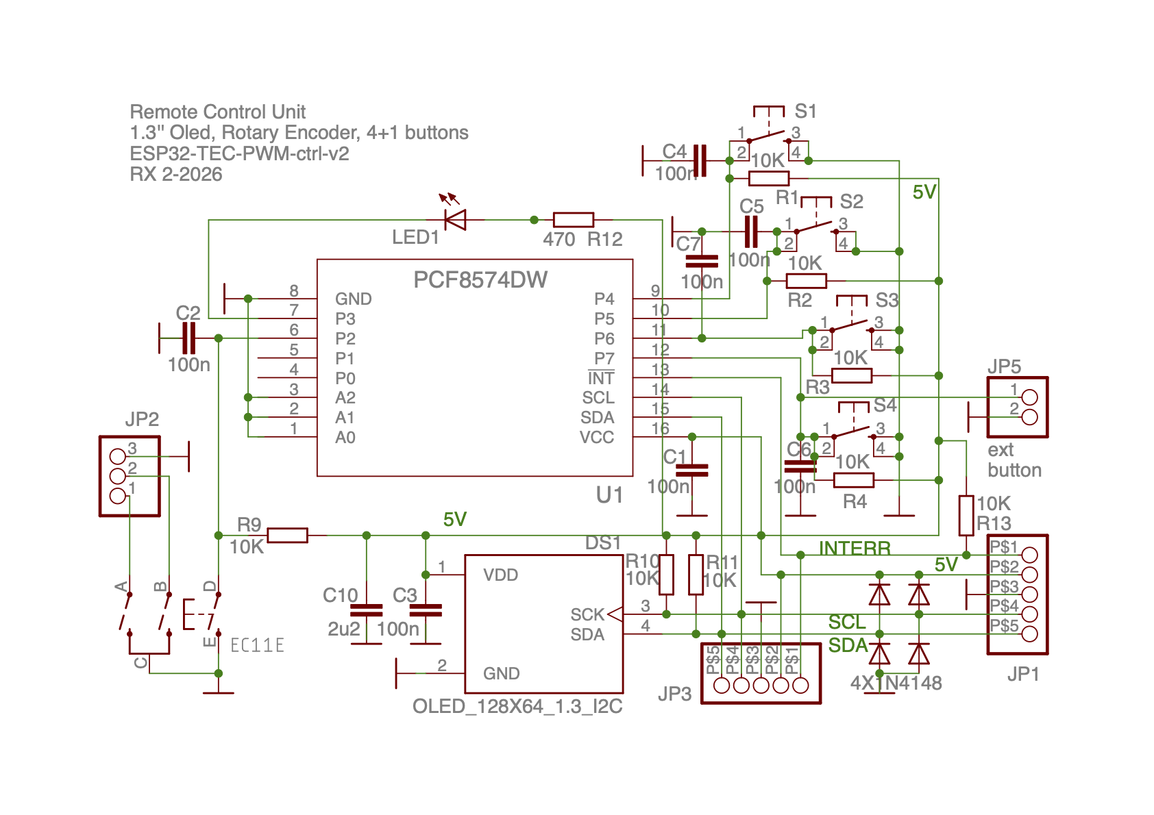
- Both JP1 and JP3 can connect to the PWM controller board, JP1 is used for shield-type connection while JP3 is intended to connect via cable. JP2 connects the rotary encoder directly to the ESP32-S3, either by shield or cable. JP5 can be used for an optional separate button, would need to be configured by the software.
Initially I thought that would require a simple rewriting of the code for my previous Arduino Uno board. However, the business with timers, interrupts and MCPWM module of the ESP32-S3 is completely different, and I have spent months (hobby time) to sort it out and optimize it. However, as mentioned above, 16bit resolution of the PWM unit does not work well beyond 120khz so that the expected reduction in filter size as compared to the Arduino Uno running at 63khz PWM speed was not as dramatic as expected. The mechanism to achieve 16bit resolution for an Arduino Uno by oversampling as was explained in detail here (essentially by folding extra bits into the time domain), and we follow the same strategy for the ESP32.
Now here some more specific points of the software:
- Essential is the arduino-esp32 library for the ESP32, and most important for us is the implementation of the hardware motor controller PWM (MCPWM) documented here; this was by far the toughest part of the project and Claude Code was of crucial help.
- Like for our Arduino project, crucial are also the PID libraries PID_v1 and PID_AutoTune_v0 which provide autotuning of PID parameters and avoid regulator windup, and which are well documented in the blog of Brett Beauregard. I use a minimally modified version of the Autotune lib that works for the "REVERSED" controller mode used now (sign flip).
- Apart from using standard libraries like Adafruit_SH110X and Adafruit-GFX-Library as well as RunningAverage and PCF8574 by RobTillaart, I also borrowed from rotaryDecoder.h and other smaller items as acknowledged in the code.
- Various hardware configuration data, like H-bridge chip, PCB board version, preamp resistor configuration, must be chosen by setting flags before compilation.
- The time budget is as follows: the PID loop updates every 50...100ms, which includes a random delay of 0...50ms in order to prevent subtle oscillations in the temperature (noise peaks showing up every couple of minutes... hard to explain). On top of that there is a slower loop for I/O and protection checks.
- There are three kinds of I/O:
- OLED Display via I2C bus. It shows temperature and (later laser diode) values and setpoints plus warnings.
- Serial I/O on the ESP32 console via USB. Right now the following commands are implemented:
a: autotune PID and save result in EEPROM toggles on/off
c: set current limit and determine max/min PWM drive limits for it and save to EEprom. Format is " c2500; " for 2500mA
d: disable remote control
e: enable remote control to input data (use before t,c,i)
h: this help
i: set laser diode current times 10. Format "i2495; " for 249.5mA /future feature
p: show stored PID and other configs
r: reset EEprom to defaults
t: set temperature setpoint times 1000. Format " t21345; " for 21.345C
y: toggle tty serial mode
- LabVIEW interface via USB as well.
LabVIEW can remotely control the Arduino by issuing "e" and then sending some of the other commands described above.
It can also read data by requesting them via the serial commands:
l: put LabVIEW read mode on (toggles tty mode off); Return format is:
<T_setpoint>T_actual>I_PWM>LD current> ... + some more for later use.
z: LabVIEW read mode off.
Example:
1) LabVIEW sends "l" to pull data
2) ESP32 sends eg. <20.0000>20.0002> -35> 112.00> 0.00>0.00>0.00>
3) LabVIEW sends "z" after reading
- Several protection mechanisms lead to auto-shutdown: PWM bridge temp failure, open/shorted thermistor, temperature way out of range. Also controls for values out-of-bounds are ignored.
- PID autotuning: determines and sets appropriate PID loop control parameters. Reasonable defaults are chosen to cater typical heat load situations for laser diodes, so it may not be necessary to ajust. Only for very different thermal loop characteristics, in particular if the loop oscillates, one needs to run PID autotuning once. The data will be stored automatically.
- In the PID_v1 library there is also an anti-windup feature that tells the PWM controller what the allowed min and max driver signals are, so it can adapt to it in order to avoid situations where the controller thinks that the PWM bridge can offer, say 10A, and gets stuck at 2A because the 10A are never reached. We took care that after changing the current limit, the driver steps up the drive (PWM input signal) from zero until the actual current limit (PWM output) is reached, then lets the PID loop config know about it and stores the data in EEPROM.
Under construction
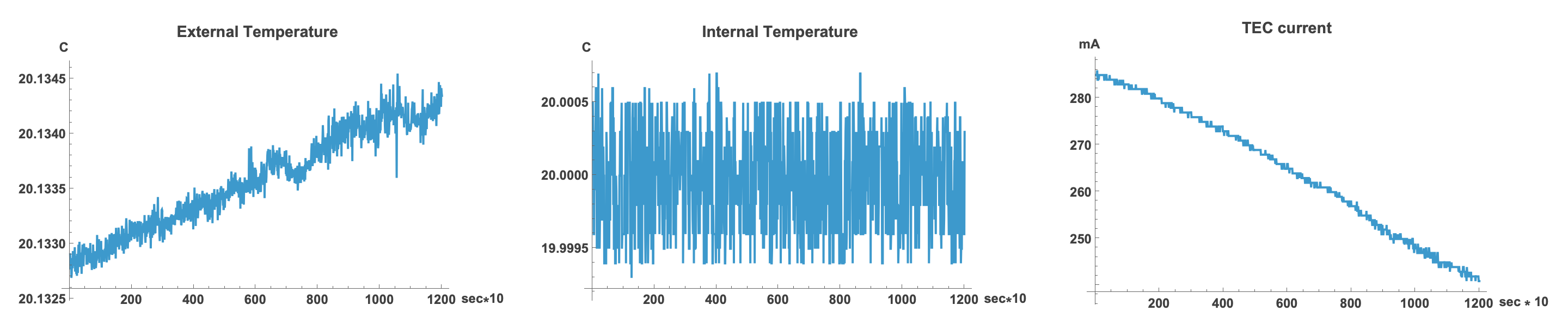
This demonstrates temperature stability for an extended period of time. To the left, we see an independent temperature measurement by an external 6 digit Rigol 3068 DMM, attached to a separate nearby thermistor on the laser diode mount. Noise is less then 0.5mK. In the middle we see the temperature as seen by the ESP32, it does not drift because the setpoint and the ADC refer to the same reference voltage. On the right the TEC current is plotted. Measurements were performed every 10sec.
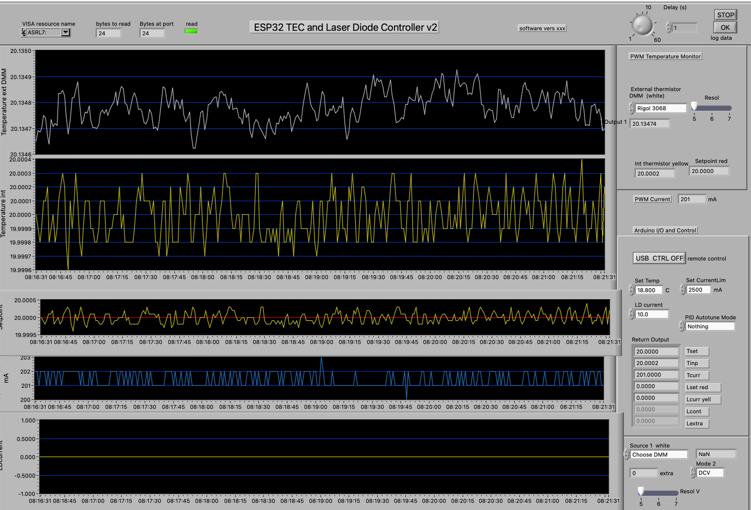
This LabVIEW interface shows short term stability:
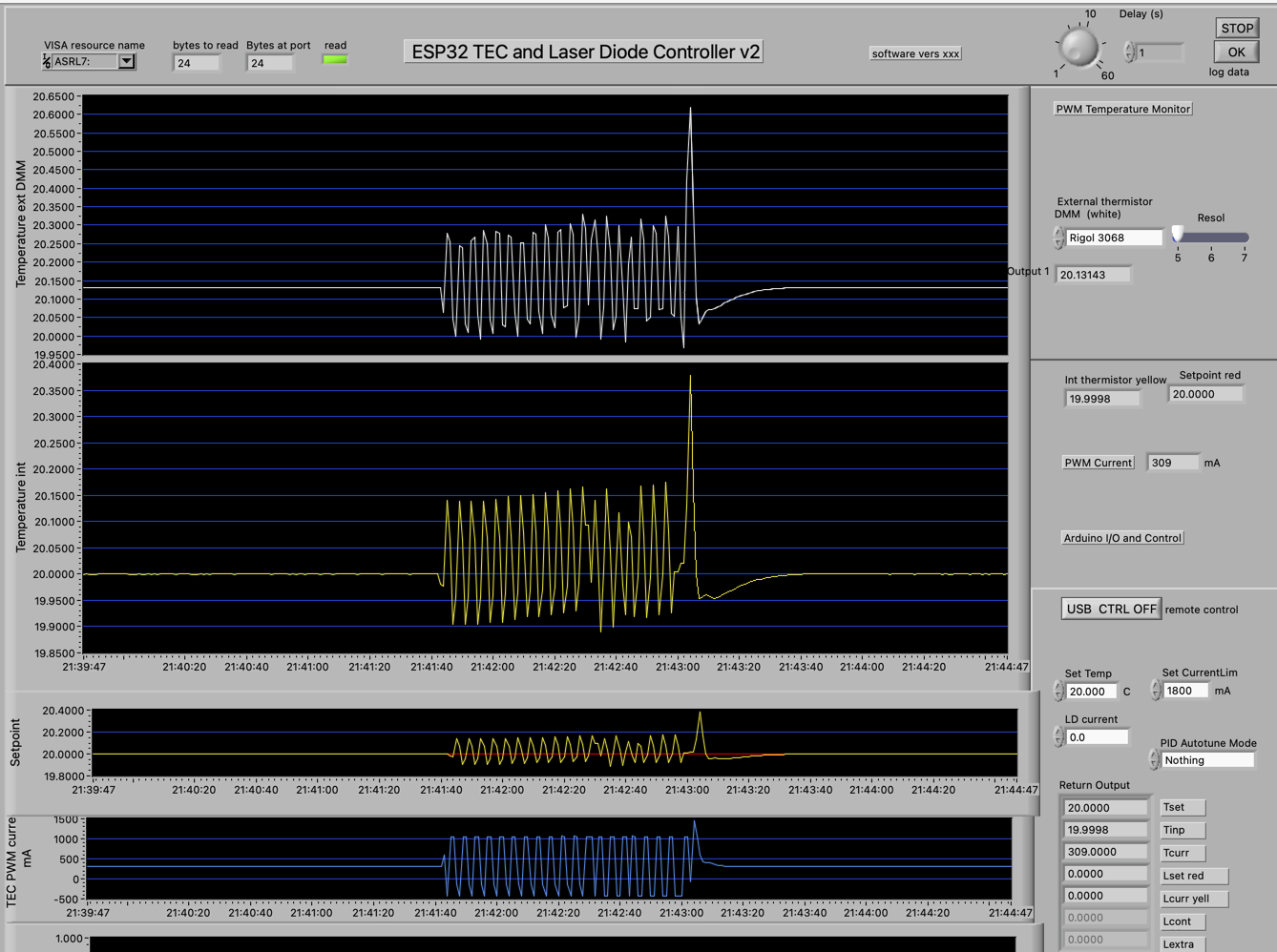
Autotuning mode samples the response under alternating current changes and computes from this the optimal configuration of the PID regulator loop:
To be continued.
Under construction
Current: Vers. 0.9 -- May 2026
Return to home page