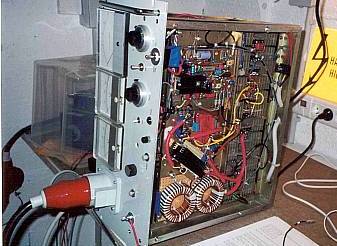
 More pictures
Return to home page
New (02/2004): The circuit has been streamlined and an relatively-easy-to-build package incl PCB layout suitable for common 10A laser heads has been put together by RichardK, which will be available soon. See below.
Building and using a switchmode power supply (SMPS) for an argon laser has many advantages as compared to easier-to-build linear regulators: no heavy and expensive transformers and tunnel coolers are necessary, one does not need to blow >500W wasted power into the air (rather there is almost no heat generated), and the output voltage can vary over a wide range, so that one doesn't need specifically tapped transformers for running various different laser heads - just connect almost any small or mid-frame ion laser (or CW Yag laser), adjust some filament, igniter and magnet voltages, and off you go ! Of course this works only for laser heads that require a bit less than rectified-mains-AC voltage, (perhaps max 250V for european 2-phase mains and perhaps max 130V for US mains, otherweise a step-up transformer or 3-phase mains is needed).
The disadvantages.... one needs a bit of patience, and "good nerves" to push this trough, being prepared for sudden bangs and puffs of smoke, and having a bunch of spare mosfets doesn't harm. Otherwise, when all is working eventually, it's mostly radio interference what is bothersome, if anything at all.
As a non-expert I had to work myself through many test setups, and it turned out that developing a powerful SMPS is quite an effort and requires a lot of spare mosfets at hand - almost every little mistake will result in a puff of smoke and shorted-out mosfets. The purpose of these notes is to share my experiences and struggles so that others may have an easier route to a decent SMPS, without falling into every possible trap. Despite I tried to be as detailed as possible, these notes are not meant to be a plan to be blindly followed, nor any guarantee for the working of the SMPS is implied (which also depends on a correct layout). Everybody has different needs and parts at hand anyway, so the following is meant to just give some inspiration and ideas. I'd be happy to include here experiences and comments of other people.
The first circuit to think about was the Omnichrome 150R Power Supply , as shown in Sam's Laser FAQ , which is an (relatively speaking) uncomplicated buck converter. However, it involves unspecified inductors, an unknown gate-drive transformer and a hall sensor which is hard and expensive to get either. So I decided to start from this circuit but modify it such as to make it as simple as possible, using only parts I have or are easy to get, in particular an opto-coupler for mosfet gate driving. Moreover I decided to abandon light control feedback because this is not of real necessity for use in hobby applications. The good thing is that for this specific application, one does not need a sophisticated feedback loop response, stability under suddenly changing loads, or immunity against output short circuit, etc; this makes the design much easier as compared to a multi-purpose lab type SMPS. Note that I omitted any interlock and other safety features in the plan, see Sam's FAQ for detailed comments on those.
There was at first some literature to read, and it became obvious that layout would be critical in order to avoid voltage spikes due to stray inductance, and other instability. I recommend, first of all, Ar/Kr Ion Laser Power Supplies and Ar/Kr Ion Laser Power Supply Design and other pages in Sam's Laser FAQ, and then Switching-Mode Power Supply Design, Ridley engineering , Philips notes on Mosfets , Philips notes on switching circuits, Switching Regulators for Poets, inductor design literature, a remarkable interactive switcher design page. Lots if useful info and further links can be found at Lazar's power electronics corner. An interesting link is also this one; finally here a link to the schematics of a commercial SMPS for OEM Lexel 88 heads.
Based on this and other info, I decided to use a specific mosfet driver IC, in order to have optimal control over pulse rise time and shape; this is crucial for having low power dissipation. Moreover, I decided to use a modular structure in order to develop and test parts of the circuit independently. Also, the spatial setup in the case is such that the heat sinks are not too close to the place where the other circuits must go. This means I had to find out a good way for using long (~30cm) connections while still having voltage spikes and radiated noise under control.
After building a few test circuits in which I investigated various possibilities for distributing the components, I found the following modular structure to work well:
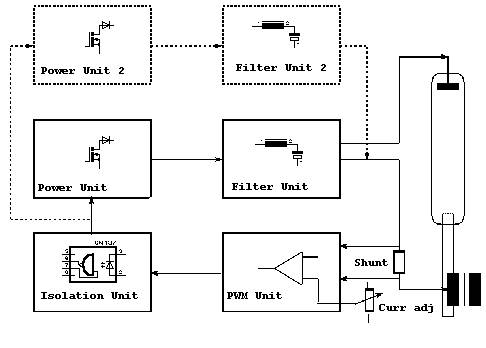
The length of the connections between the various units can be long, provided one uses shielded cables. The second power and filter units are optional and are required if one wants to double to current capacity from (at least) ca 15A to (at least) ca 30A (the ultimate capacity is mainly a problem of heat and I didn't check beyond 30A at 200V in order not to risk a blowup. Certain things --mainly shunt resistors, rectifier, cabling, not so much the mosfets-- tend to get quite warm above 25A, and in order to reach much higher currents, one may need larger sinks and/or forced air cooling).
The detailed circuit diagram is here (ca 400KB .pdf; drawn for a single copy of power and filter units, resp).
The individual building blocks are in detail described here:
Because I am lazy I didn't do any PCB but all the circuits are made on single-side clad epoxy boards, with the components soldered on the copper side (and on "mini-mounts" ). This high-frequency "ground plane" circuitry gives low-inductance ground connections. However, the different modules use different grounds (sometimes with full high voltage difference) and also float with respect to true mains ground. This means the copper side grounds must be all isolated from the true mains ground.
1) I have successfully connected my new Lexel 88 head and it runs very fine with the SMPS (actually it is right now more than 2 years running without a glitch), absolutely stable with less than 1% noise in the light output (so far tested up to 30A incl 3A magnet current); see here for details.
2) RFI: Clearly a powerful SMPS is prone to create lots of interference, both by radiated radio frequency and directly via the mains line. So far I didn't care about this at all, living in a single-family home. But for more responsible people some precautions should be taken, like adding RF chokes in the mains and laser output lines, and perhaps as well a large choke between the rectifier and the main filter caps. Indeed without the latter the mains input current is anything else than sinusoidal....
3) Safety: The 310VDC power comes into this circuit directly from rectified 230VAC mains, without transformer. Needless to say that a temporary isolation transformer greatly reduces the high voltage risk while setting up this circuit (ultimately, the whole point is of course to avoid transformers altogether). I also always use rubber gloves as first protection when approaching the circuit when live. Others recommend even to wear safety goggles when trying out such a circuit, because when a capacitor or transistor blows, bits and pieces can fly all over.
It is obvious that this circuit is by far not as simple as a linear regulator and requires some experience to build; absolutely necessary is a >=10Mhz oscilloscope with floating ground (eg, a battery driven one), for checking the correct waveforms, in particular arpund the mosfets.
Disclaimer: The information given here is meant to help people to construct their own SMPS, and not as a fool-proof plan. To build such a thing requires good knowledge of electronics and is not a beginner's project, especially also because the voltages and currents involved are life-threatening and one really needs to know how to handle this in a safe way. I do not assume any responsibility for personal and/or property damage that may result when trying to set up the circuit described here, and emphasize that suitable cases, wirings and safety interlocks for preventing electric shock and exposure to laser radiation must be implemented by law, despite not being shown in the plans here.
4) Here a zipped Mathematica notebook with some computations and simulations.
5) Electronics/data sheets for the semiconductors used, with some alternatives (roughly ordered according to suitability; the selection is mostly according what I happened to have around, ie., quite random):
6) New (2/2004): the circuit has been streamlined by RichardK, by substituting the DC/DC converter by a separate auxiliary supply for the PWM chip, and in a later (not the current) version the 50W sense resistor will be replaced by a more power-efficient Hall sensor. All the updated schematics, PCB layouts and Farnell part numbers packaged together can be obtained soon from here. This circuit is primarily meant as a low-power (appr 10A) version for standard air cooled argon heads like the ALC60 (for more power, several mosfet and inductor units can be added in parallel as described above). See his site (in german).
Return to home page